
Daytona Shelby V6-181 3.0L SOHC (1991)
Body Controller: Connector Views
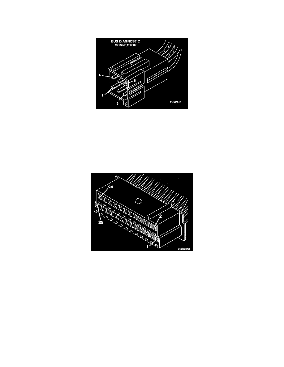
Bus Diagnostic Connector
CAV CIRCUIT
FUNCTION
1
D11 2OWT/VT
Data In
2
F30 18RD
Battery 12V
3
D02 2OWT/BK
Serial Data Bus (-)
4
DO1 20VT/BR
Serial Data Bus (+)
5
D12 20OR
Data Out
6
Z02 18BK/LG
Ground
Body Computer Premium Connector (Black)
CONNECTOR VIEWED FROM TERMINAL END
CAV CIRCUIT
FUNCTION
1
G16 BK/LB
Left Front Door Jamb Switch
2
G75 TN
Door Ajar Left Front Door
3
G10 LG/RD
Seat Belt Warning Switch
4
G26 LB
Key In Chime
5
L61 LG
Left Turn Signal
6
E17 YL/BK
Step Dimmer Switch
7
M22 WT
Illuminated Entry Feed
8
P31 OR/BK
Power Door Lock Input (Switched Feed)
9
V0g BK
Intermittent Wiper Level
10
V10 BR
Front Windshield Washer Switch
11
GO4 DB
Fuel Level
12
GO5 DB/WT
Ignition Feed (Run)
13
Z02 BK/LG
Electronic Ground
14
DO1 VT/BR
Serial Data Bus (+)
15
D02 WT/BK
Serial Data Bus (-)