
Daytona Shelby Z L4-135 2.2L SOHC Turbo VIN E FI (1988)
Shift Linkage: Adjustments
Rod Linkage
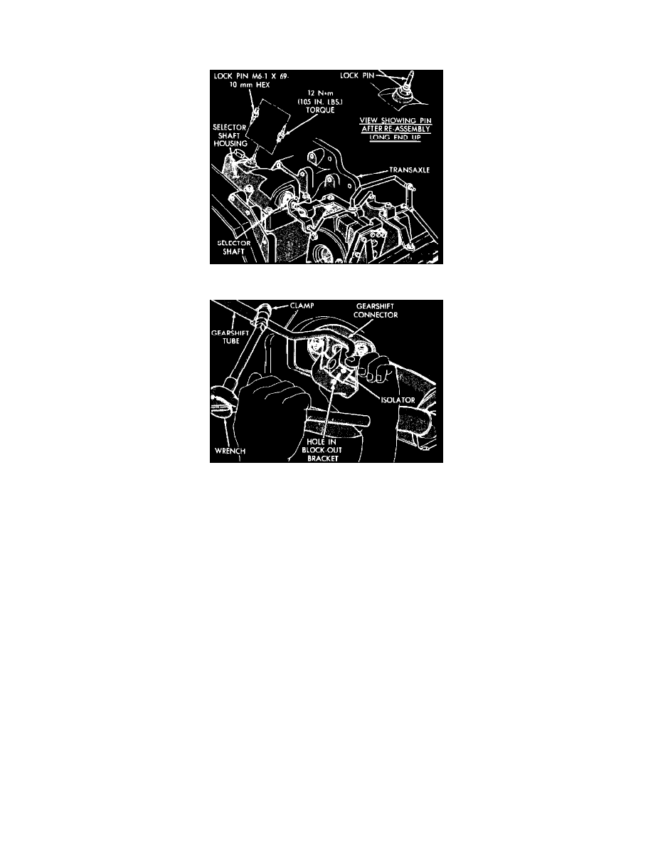
Fig. 7 Lock pin removal & installation
Fig. 8 Adjusting rod-type gear shift linkage
1. Remove lock pin from transaxle selector shaft housing.
2. Reverse lock pin so long end is facing downward, and insert pin into same threaded hole while pushing selector shaft into selector housing.
3. Raise and support vehicle then loosen clamp bolt that secures gearshift tube to gearshift rod.
4. Check that gearshift connector slides and rotates freely in gearshift tube.
5. Position shifter mechanism connector assembly so that isolator is spaced 0.050 inch away from upstanding flange, while rib on isolator is aligned
fore and aft with hole in blocker bracket. Hold connector isolator in this position and torque clamp bolt on gearshift tube to 170 inch lbs. No
significant force should be placed on linkage during this procedure.
6. Lower vehicle, remove lock pin from selector shaft housing and reinstall lock pin in reversed position. Torque pin to 105 in. lbs.
7. Check for proper operation.