
Diplomat V8-318 5.2L VIN K 2-bbl (1982)
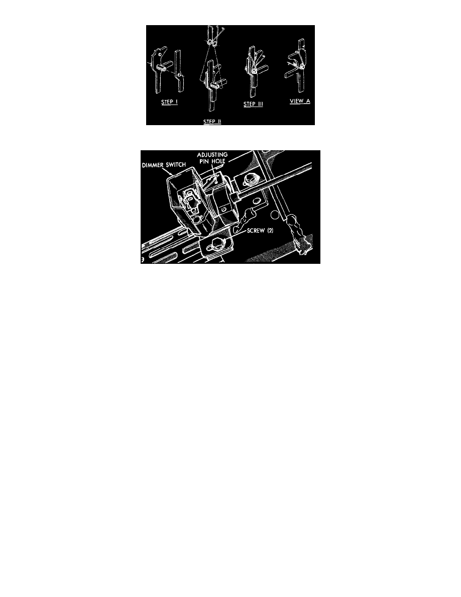
Fig. 13 Lock lever & spring assembly. Models w/standard column exc. Horizon & Omni; 1983---87 Charger & Turismo; 1985---87 Daytona & Laser
Fig. 14 Typical column mounted dimmer switch installation
Lubricate steering shaft support bearings and column friction surfaces with Grade 2 E.P. multipurpose grease prior to assembly.
1. Install toe plate and grommet on lower end of column.
2. Slide gearshift housing extension onto column, if equipped, with tabs facing upper end of column.
3. Position gearshift housing on upper end of column, ensuring that support is properly seated against mast jacket tabs.
4. On floor shift models, install rubber bumper and spring securing shift housing to mast jacket.
5. On column shift models, ensure that dust sleeve and support bushing are properly installed, then slide shift tube in from lower end of column,
guiding key on upper end of tube into slot in gearshift housing.
6. Hold shift tube and housing together firmly, then tighten setscrew to secure shift tube.
7. On models with plastic housing, ensure that shift tube key is started into housing slot, install tools C-4584 and C-4584-2, and pull shift tube into
gearshift housing.
8. Position crossover load spring and gearshift lever in housing, then secure lever with retaining pin.
9. Assemble key cylinder plunger and spring, then install plunger and spring assembly and shift gate on lock housing.
10. Insert ignition switch rod through shift housing.
11. Place shift lever in mid position and position lock housing assembly on mast jacket, guiding ignition switch rod through oval shaped hole and
indexing key way in housing with slot in jacket.
12. Insert 4 lock housing retaining screws and tighten screws alternately and evenly, torquing screws to 90 inch lbs. in several steps.
13. Lubricate and assemble lock lever and spring assembly, then install assembly in lock, seating pin firmly in bottom of slots and ensuring that spring
leg is in place in lock casting notch.
14. Place gearshift lever in "park" position, position bellcrank assembly into lock housing and insert ignition switch actuating rod into bellcrank while
pulling actuator rod down column, then install bellcrank into mounting surface.
15. Install ignition switch onto actuator rod and rotate switch 90° to lock actuating rod position.
16. Rotate ignition lock to "lock" position and remove key. Insert lock cylinder into bore until it contacts switch actuator, then insert key and rotate
cylinder while pressing inward until components align and cylinder snaps into place.
17. Feed key warning switch harness behind post and down through channel between housing and mast jacket, then remove ignition key and secure
switch.
18. On floor shift models, install lower bearing support on steering shaft, then on all models, install bearing and spring on shaft and insert shaft
through lower end of column.
19. Lubricate inside of steering shaft lock plate, then install lock plate and spring.
20. Ensure that bearing is properly seated in upper bearing housing, then install upper bearing housing and retaining screws and torque screws to
specifications.
21. Press steering shaft into column to compress springs and install upper bearing snap ring.
22. Reverse remaining procedure to complete assembly, noting the following:
a. Install dimmer switch actuator rod up through housing into pocket of washer/wiper switch, compress switch and install 0.093 inch rod into
adjusting hole, mount switch and apply slightly upward pressure against actuator rod, then tighten retaining screws and remove rod from hole.