
Durango 2WD V6-3.7L (2009)
Brake Light Switch: Service and Repair
Stop Lamp Switch - Installation
INSTALLATION
WARNING: To avoid serious or fatal injury on vehicles equipped with airbags, disable the Supplemental Restraint System (SRS) before
attempting any steering wheel, steering column, airbag, seat belt tensioner, impact sensor or instrument panel component
diagnosis or service. Disconnect and isolate the negative battery (ground) cable. Wait two minutes for the system capacitor to
discharge before performing further diagnosis or service. On vehicles equipped with the optional Hybrid Electric Vehicle (HEV)
system, a technician trained in proper HEV service safety procedures must also remove the high voltage service disconnect from
the high voltage battery pack. This is the only sure way to disable the SRS. Failure to take the proper precautions could result in
accidental airbag deployment. Failure to follow these instructions may result in possible serious or fatal injury.
CAUTION: The brake lamp switch self-adjusting switch plunger is a one time only feature. If the switch is removed from the mounting
bracket, it MUST be replaced with a new switch.
CAUTION: The brake lamp switch plunger MUST be in the fully extended position prior to releasing the brake pedal or setting the plunger
length to ensure proper switch adjustment and operation. Do not manually press the plunger into the switch body prior to or
during switch installation, and do not pull the brake pedal upward prior to setting the plunger length using the plunger
adjustment release lever as described in the following procedure.
1. Depress and hold the brake pedal in the depressed position.
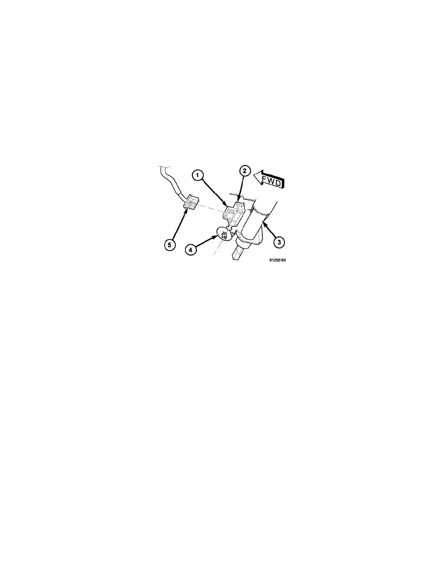
2. Align the tabs on the brake lamp switch locking collar with the keyed hole in the switch mounting bracket (4) on the lower steering column (3).
3. Insert the tabs on the brake lamp switch locking collar through the keyed hole in the switch mounting bracket until the switch housing (1) is firmly
seated against the bracket.
4. Rotate the switch housing counterclockwise about 30 degrees to engage the tabs on the locking collar with the switch mounting bracket.
CAUTION: Release, but do not pull up on the brake pedal before the switch plunger adjustment has been completed.
5. Release the brake pedal, but do not pull it upward.
CAUTION: Be certain that the brake lamp switch plunger is in contact with the flag bracket on the brake pedal arm prior to rotating the
plunger adjustment release lever. If the plunger is not contacting the flag bracket, depress and hold the brake pedal while
manually pulling the plunger out from the switch body to the fully extended position. Then release the brake pedal, but do not pull
it upward.
6. Rotate the plunger adjustment release lever (2) clockwise until it locks into place. The lever should be parallel to the brake lamp switch connector
receptacle. This action will set the switch plunger length to a final adjustment position and cannot be undone. If not performed properly the first
time, a new brake lamp switch must be installed.
7. Reconnect the wire harness connector (5) to the brake lamp switch.
8. Reconnect the battery negative cable. On vehicles equipped with the optional Hybrid Electric Vehicle (HEV) system, a technician trained in
proper HEV service safety procedures must also reinstall the high voltage service disconnect into the high voltage battery pack.