
Durango 2WD V6-3.7L (2009)
CAUTION: If the clockspring is not properly centered in relation to the Steering Angle Sensor (SAS), steering wheel, steering shaft and
steering gear, it may be damaged or Diagnostic Trouble Codes (DTC) may be set in the SAS. See: Procedures . Service replacement
clocksprings are shipped pre-centered and with a locking pin installed. This locking pin should not be removed until the
clockspring has been installed on the steering column.
NOTE: Before starting this procedure, be certain that the front wheels are still in the straight-ahead position.
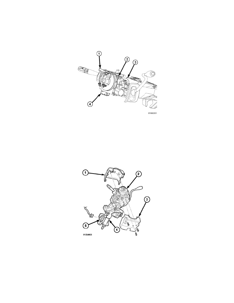
1. While holding the centered clockspring rotor and case stationary in relation to each other, or with the plastic locking pin (1) installed, carefully
slide the clockspring (4) down over the steering column (3) upper shaft.
2. Align and seat the hole in the locating tab on the clockspring case over the locating pin on the multi-function switch mounting housing.
3. Install and tighten the two screws (2) that secure the clockspring to the multi-function switch mounting housing. Tighten the screws to 2 Nm (20
in. lbs.).
4. Reconnect the two instrument panel wire harness connectors to the two connector receptacles located below the steering column on the back of the
clockspring housing.
5. Reconnect the instrument panel wire harness connector to the applied connector for the Steering Angle Sensor (SAS) located below the steering
column on the back of the clockspring housing.
6. Position the lower shroud (3) onto the steering column (4).
7. From below the steering column, install and tighten the one center screw that secures the lower shroud to the steering column. Tighten the screw to
2 Nm (20 in. lbs.).
8. Position the upper shroud (1) onto the steering column over the lower shroud. Be certain to engage the gearshift lever gap hider into the opening in
the right side of both shroud halves.
9. Align the snap features on the upper shroud with the receptacles in the lower shroud and apply hand pressure to snap them together.
10. Install and tighten the two outboard screws that secure the upper shroud to the lower shroud. Tighten the screws to 2 Nm (20 in. lbs.).