
Durango 2WD V6-3.7L (2009)
Windshield Washer Switch: Service and Repair
Multifunction Switch - Installation
INSTALLATION
WARNING: To avoid serious or fatal injury on vehicles equipped with airbags, disable the Supplemental Restraint System (SRS) before
attempting any steering wheel, steering column, airbag, seat belt tensioner, impact sensor or instrument panel component
diagnosis or service. Disconnect and isolate the negative battery (ground) cable. Wait two minutes for the system capacitor to
discharge before performing further diagnosis or service. On vehicles equipped with the optional Hybrid Electric Vehicle (HEV)
system, a technician trained in proper HEV service safety procedures must also remove the high voltage service disconnect from
the high voltage battery pack. This is the only sure way to disable the SRS. Failure to take the proper precautions could result in
accidental airbag deployment. Failure to follow these instructions may result in possible serious or fatal injury.
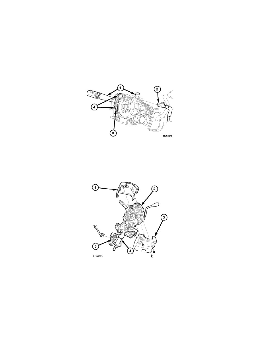
1. Slide the multi-function switch (1) into the multi-function switch mounting housing (3) from the left side. Be certain that the alignment pins on the
top and bottom of the switch are properly engaged in the channels of the mounting housing.
2. Rotate the steering wheel far enough to install and tighten the two screws (4) that secure the switch to the mounting housing. Tighten the screws to
2 Nm (20 in. lbs.).
3. Reconnect the wire harness connector (2) to the back of the switch.
4. Position the lower shroud (3) onto the steering column (4).
5. From below the steering column, install and tighten the one center screw that secures the lower shroud to the steering column. Tighten the screw to
2 Nm (20 in. lbs.).
6. Position the upper shroud (1) onto the steering column over the lower shroud. Be certain to engage the gearshift lever gap hider into the opening in
the right side of both shroud halves.
7. Align the snap features on the upper shroud with the receptacles in the lower shroud and apply hand pressure to snap them together.
8. Install and tighten the two outboard screws that secure the upper shroud to the lower shroud. Tighten the screws to 2 Nm (20 in. lbs.).