
Durango 2WD V8-5.2L VIN Y (1999)
Fuse Block: Description and Operation
DESCRIPTION
Junction Block
Junction Block
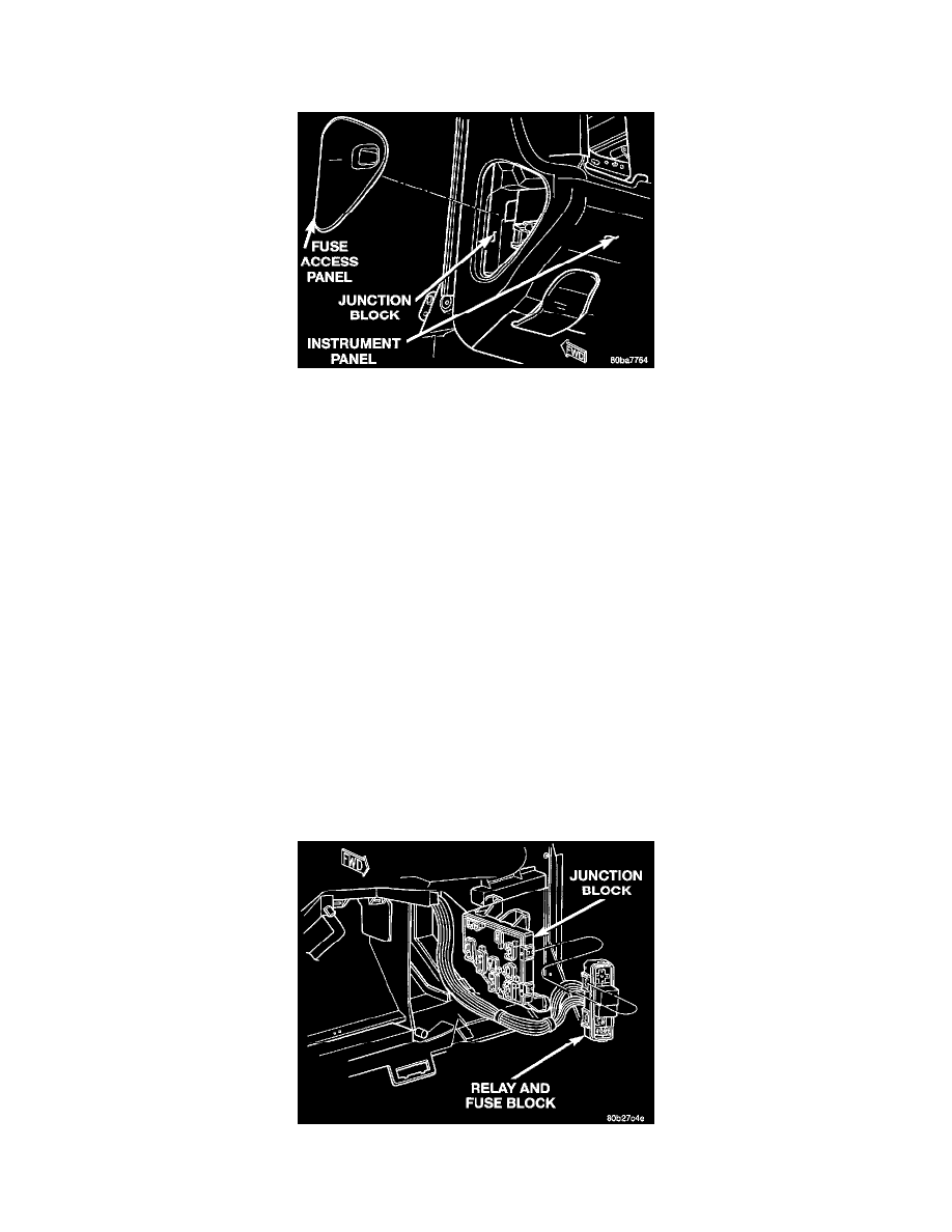
An electrical Junction Block (JB) is concealed behind the left outboard end of the instrument panel cover. The molded plastic JB housing has
integral mounting brackets that are secured with two screws to the left instrument panel end bracket. The left end of the instrument panel cover has
a snap-fit fuse access panel that can be removed for service of the junction block fuses. A fuse puller and spare fuse holders are located on the
back of the fuse access cover, as well as an adhesive-backed fuse layout label to ensure proper fuse identification.
The JB combines the functions previously provided by a separate fuseblock module and relay center, serves to simplify and centralize numerous
electrical components, and to distribute electrical current to many of the accessory systems in the vehicle. It also eliminates the need for numerous
splice connections and serves in place of a bulkhead connector between many of the engine compartment, instrument panel, and body wire
harnesses.
All of the circuits entering and leaving the JB do so through up to nine wire harness connectors, which are connected to the JB through integral
connector receptacles molded into the JB housing. The JB houses up to nineteen blade-type fuses (two standard-type and seventeen mini-type), up
to two blade- type automatic resetting circuit breakers, and two International Standards Organization (ISO) relays (one standard-type and one
micro-type). Internal connection of all of the JB circuits is accomplished by an intricate combination of hard wiring and bus bars.
The fuses, circuit breakers, and relays are available for service replacement. The JB unit cannot be repaired and is only serviced as an assembly. If
any internal circuit or if the JB housing is faulty or damaged, the entire JB unit must be replaced.
Relay And Fuse Block
An additional relay and fuse block is used on this model. The relay and fuse block is snap fit onto mounting tabs located on the end of the Junction
Block (JB) nearest to the dash panel, under the left outboard end of the instrument panel. The relay and fuse block provides additional capacity for
distribution and control of electrical current for some of the accessory systems that are unique to this vehicle, and which could not be
accommodated by the Junction Block (JB) or the Power Distribution Center (PDC).
Relay And Fuse Block