
Durango 2WD V8-5.2L VIN Y (1999)
Central Timer Module: Description and Operation
General Information
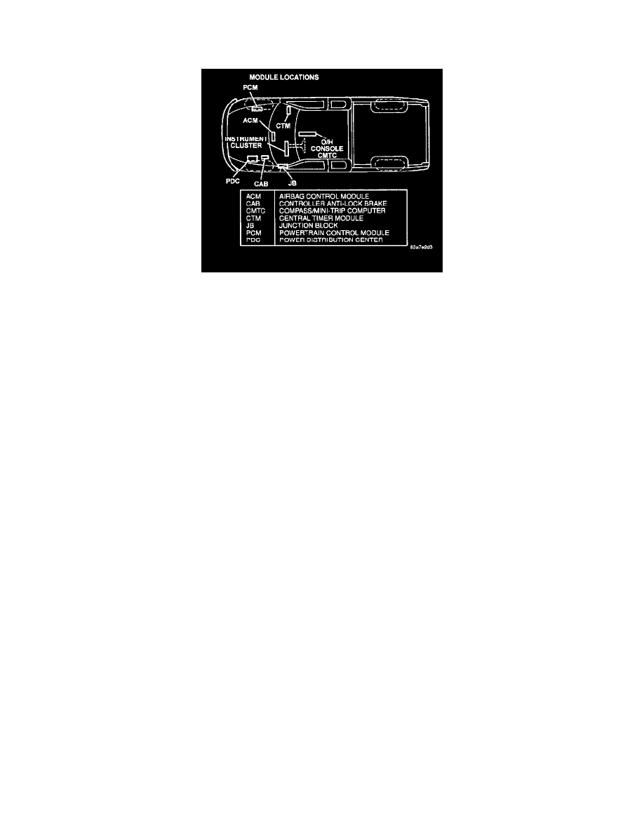
Module Locations
SYSTEM DESCRIPTION AND FUNCTIONAL OPERATION
The body system on the 1999 Durango consists of five modules that communicate over the CCD bus (Chrysler Collision Detection multiplex
system). There are two additional modules, the Powertrain Control Module (PCM) and the Controller Anti-Lock Brake (CAB) that are not part of
the body system, but do utilize the CCD bus for communication, The CAB also utilizes the bus for diagnostics. The PCM sends and receives
messages on the CCD bus, however diagnostics are performed through the Serial Communication Interface (SCI), the same as previous years. All
of the information about the functioning of all the systems is organized, controlled, and communicated by the CCD bus, which is described in
Vehicle Communication.
Through the CCD bus, information about the operation of vehicle components and circuits is relayed quickly to the appropriate module(s). All
modules receive all the information transmitted on the bus even though a module may not require all the information to perform it's function. It
will only respond to messages "addressed" to it through a binary coding process. This method of data transmission significantly reduces the
complexity of the wiring in the vehicle and the size of wiring harnesses.
AIRBAG SYSTEM
The airbag system is designed to provide increased driver and passenger protection if the vehicle is involved in a front end collision. The system is
most effective when used in conjunction with the seat belt system.
The Airbag Control Module (ACM) is an electronic module that monitors the airbag system for proper operation, stores diagnostic trouble code
(DTCs), controls the airbag warning lamp and contains the sensor and actuator that is responsible for airbag deployment. There are no external
impact sensors. The ACM is mounted on a special bracket that is fastened to the floor of the truck at the bottom of the instrument panel. It is
located forward of the console. The ACM provides diagnostic information (DTCs) to the technician through the DRB III via the CCD bus. Some
circuits are tested continuously; others are checked only under certain circumstances. The warning lamp is driven with messages relayed to the
Mechanical Instrument Cluster (MIC) from the ACM via the CCD bus.
The AIRBAG warning lamp is the only point at which "symptoms" of a system malfunction can be observed by the customer. whenever the
ignition key is turned to the "RUN" or "START" position, the Airbag Control Module performs a lamp check by turning the AIRBAG warning
lamp ON for 6-8 seconds. If the lamp remains OFF, it means that the ACM has checked the system and found it to be free of discernible
malfunctions. If the lamp remains ON, there could be an active fault in the system or the circuit that operates the lamp may be shorted to ground. If
the lamp comes ON and stays ON for a period longer than 6-8 seconds, then goes OFF, there is usually an intermittent problem in the system.
Perform the WARNING LAMP CIRCUIT OPEN procedure in this book to find the cause of any customer complaint regarding the AIRBAG
warning lamp, such as:
-
warning lamp does not illuminate
-
warning lamp stays illuminated
WARNING: THE AIRBAG CONTROL MODULE CONTAINS THE IMPACT SENSOR, WHICH ENABLES THE SYSTEM TO
DEPLOY THE AIRBAG. BEFORE ATTEMPTING TO DIAGNOSE OR SERVICE ANY AIRBAG SYSTEM OR RELATED
STEERING WHEEL,STEERING COLUMN, OR INSTRUMENT PANEL COMPONENTS YOU MUST FIRST DISCONNECT AND
ISOLATE THE BATTERY NEGATIVE (GROUND) CABLE. THEN WAIT TWO MINUTES FOR THE SYSTEM CAPACITOR TO
DISCHARGE BEFORE FURTHER SYSTEM SERVICE. THIS IS THE ONLY SURE WAY TO DISABLE THE AIRBAG SYSTEM.
FAILURE TO DO THIS COULD RESULT IN ACCIDENTAL AIRBAG DEPLOYMENT AND POSSIBLE PERSONAL
INJURY.NEVER STRIKE OR KICK THE AIRBAG CONTROL MODULE, AS IT CAN DAMAGE THE IMPACT SENSOR OR