
Durango 2WD V8-5.2L VIN Y (1999)
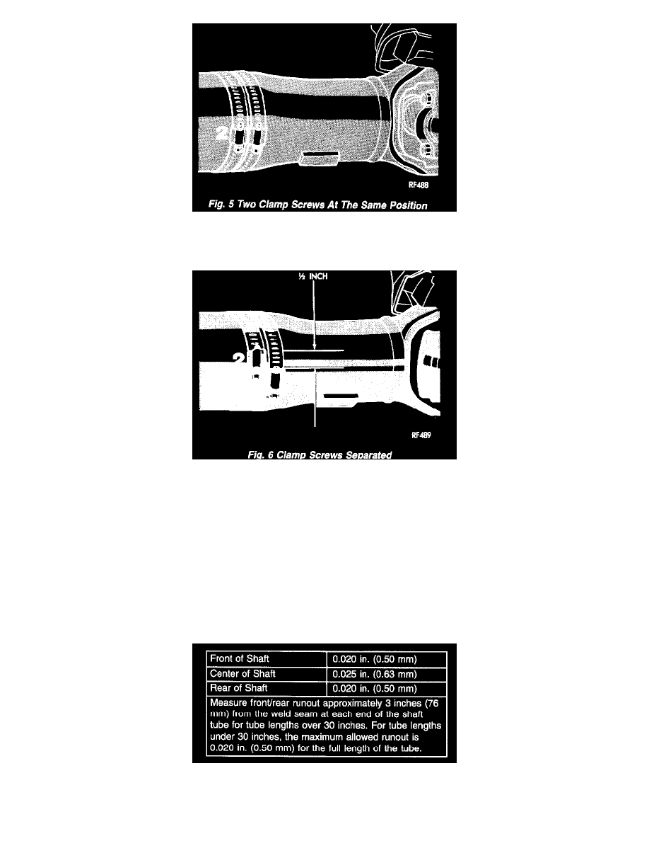
Fig. 5
12. If the vibration decreased, install a second clamp and repeat the test.
Fig. 6
13. If the additional clamp causes an additional vibration, separate the clamps (1/4 inch above and below the mark). Repeat the vibration test.
14. Increase distance between the clamp screws and repeat the test until the amount of vibration is at the lowest level. Bend the slack end of the clamps
so the screws will not loosen.
15. If the vibration remains unacceptable, apply the same steps to the front end of the propeller shaft.
16. Install the wheel and tires. Lower the vehicle.
Runout
1. Remove dirt, rust, paint, and undercoating from the propeller shaft surface where the dial indicator will contact the shaft.
2. The dial indicator must be installed perpendicular to the shaft surface.
3. Measure runout at the center and ends of the shaft sufficiently far away from weld areas to ensure that the effects of the weld process will not enter
into the measurements.
4. Refer to Runout Specifications chart.
5. If the propeller shaft runout is out of specification, remove the propeller shaft, index the shaft 180°, and re-install the propeller shaft. Measure
shaft runout again