
Durango 2WD V8-5.9L VIN Z LDC (2000)
All of the current from the battery and the generator output enters the PDC through two cables with eyelets that are secured with nuts to the two
B(+) terminal studs located just inside the inboard side of the PDC housing. The PDC cover is unlatched and removed to access the battery and
generator output connection B(+) terminal studs, the fuses, the relays, the joint connectors and the engine wire harness inline connector. Internal
connection of all of the PDC circuits is accomplished by an intricate combination of hard wiring and bus bars.
GENERATOR CARTRIDGE FUSE
A 140 ampere generator cartridge fuse is used on this model. The generator cartridge fuse is similar to other cartridge fuses found in the Power
Distribution Center (PDC). This fuse has a color-coded plastic housing and a clear plastic fuse conductor inspection cover like other cartridge
fuses, but has a higher current rating and is connected and secured with screws instead of being pushed onto male spade-type terminals. The
generator cartridge fuse cannot be repaired and, if faulty or damaged, it must be replaced.
The generator cartridge fuse is secured between the two B(+) terminal stud connection bus bars within the Power Distribution Center (PDC). This
fuse protects the vehicle electrical system from damage that could be caused by excessive charging system output and/or excessive electrical
system current levels resulting from a faulty generator or faulty charging system control circuits. If the current rating of the fuse is exceeded, the
fuse conductor melts to open the generator output circuit connection to the PDC. If a generator cartridge fuse fails, be certain to completely inspect
and test the vehicle charging system before replacing the fuse and returning the vehicle to service.
JUNCTION BLOCK
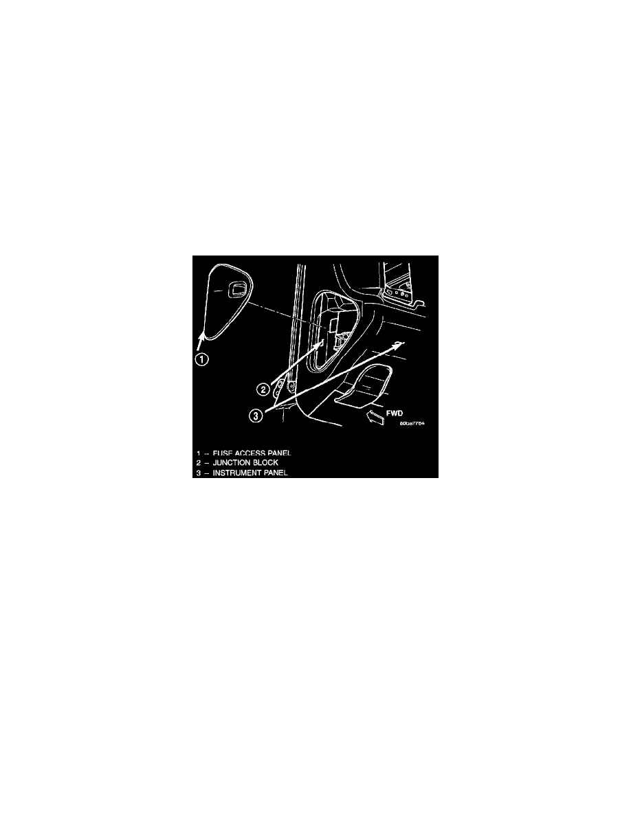
Junction Block Location
An electrical Junction Block (JB) is concealed behind the left outboard end of the instrument panel cover. The JB serves to simplify and centralize
numerous electrical components, and to distribute electrical current to many of the accessory systems in the vehicle. It also eliminates the need for
numerous splice connections and serves in place of a bulkhead connector between many of the engine compartment, instrument panel, and body
wire harnesses. The JB houses up to nineteen blade-type fuses (two standard-type and seventeen mini-type), up to two blade- type automatic
resetting circuit breakers, and two International Standards Organization (ISO) relays (one standard-type and one micro-type).
The molded plastic JB housing has integral mounting brackets that are secured with two screws to the left instrument panel end bracket. The left
end of the instrument panel cover has a snap-fit fuse access panel that can be removed for service of the JB. A fuse puller and spare fuse holders
are located on the back of the fuse access cover, as well as an adhesive- backed fuse layout map to ensure proper fuse identification.
The JB unit cannot be repaired and is only serviced as an assembly. If any internal circuit or the JB housing is faulty or damaged; the entire JB unit
must be replaced.
All of the circuits entering and leaving the JB do so through up to nine wire harness connectors, which are connected to the JB through integral
connector receptacles molded into the JB housing. Internal connection of all of the JB circuits is accomplished by an intricate combination of hard
wiring and bus bars.
IGNITION-OFF DRAW FUSE