
Durango RT 4WD V8-5.9L VIN Z LDC (2002)
Wiper Relay: Testing and Inspection
Rear Wiper Relay Test
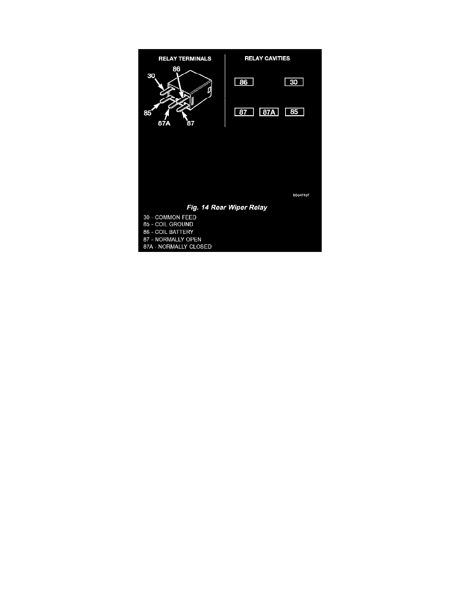
Fig.14 Rear Wiper Relay
The rear wiper relay is located in the Power Distribution Center (PDC) in the engine compartment. See the fuse and relay layout label affixed to the
inside surface of the PDC cover for rear wiper relay identification and location. Refer to the appropriate wiring information. The wiring information
includes wiring diagrams, proper wire and connector repair procedures, details of wire harness routing and retention, connector pin-out information and
location views for the various wire harness connectors, splices and grounds.
1. Remove the rear wiper relay from the PDC. (Refer to ELECTRICAL/REAR WIPERS/WASHERS/REAR WIPER RELAY - REMOVAL).
2. A relay in the de-energized position should have continuity between terminals 87A and 30, and no continuity between terminals 87 and 30. If OK,
go to Step 3. If not OK, replace the faulty relay
3. Resistance between terminals 85 and 86 (electromagnet) should be 75 ± 5 ohms. If OK, go to Step 4. If not OK, replace the faulty relay.
4. Connect a battery to terminals 85 and 86. There should now be continuity between terminals 30 and 87, and no continuity between terminals 87A
and 30. If OK, test the relay input and output circuits. Refer to RELAY CIRCUIT TEST . If not OK, replace the faulty relay.
Relay Circuit Test
1. The relay common feed terminal cavity (30) is connected to the multi-function switch. There should be continuity between the receptacle for
terminal 30 of the rear wiper relay in the PDC and the rear wiper motor control circuit cavity of the liftgate wire harness connector for the rear
wiper motor at all times. If OK, go to Step 2. If not OK, repair the open rear wiper motor control circuit between the PDC and the rear wiper
motor as required.
2. The relay normally closed terminal (87A) is connected to ground. There should be continuity between the receptacle for terminal 87A of the rear
wiper relay in the PDC and a good ground at all times. If OK, go to Step 3. If not OK, repair the open ground circuit to ground (G113) as required.
3. The relay normally open terminal (87) is connected to a fused B(+) fuse in the PDC through a fused B(+) circuit. There should be battery voltage
at the receptacle for terminal 87 of the rear wiper relay at all times. If OK, go to Step 4. If not OK, repair the open B(+) circuit between the PDC
and the battery as required.
4. The coil battery terminal (86) is connected to a fused B(+) fuse in the PDC through a fused B(+) circuit. There should be battery voltage at the
receptacle for terminal 86 of the rear wiper relay at all times. If OK, go to Step 5. If not OK, repair the open B(+) circuit between the PDC and the
battery as required.
5. The coil ground terminal (85) is connected to the output of the Central Timer Module (CTM) through the rear wiper relay control circuit. There
should be continuity between the receptacle for terminal 85 of the rear wiper relay in the PDC and the rear wiper relay control circuit cavity of the
instrument panel wire harness connector (Connector C3) for the CTM at all times. If not OK, repair the open rear wiper relay control circuit
between the PDC and the CTM as required.