
Dynasty L4-153 2.5L SOHC (1988)
Fuel Injector: Description and Operation
Fuel System Controls
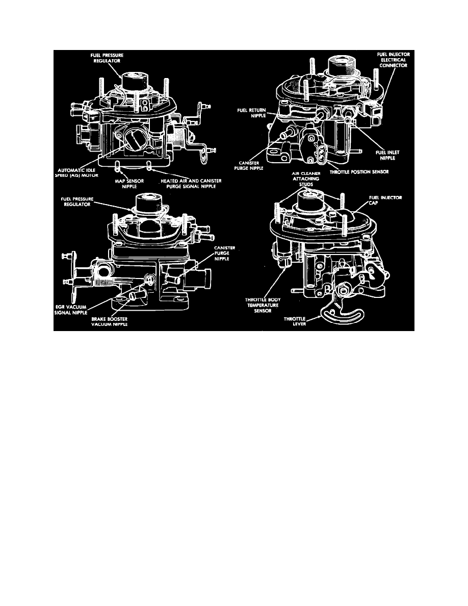
Fig. 4 Throttle body assembly component identification. 1988-90 models
Throttle Body & Fuel Injector
The throttle body assembly is mounted on the intake manifold and houses the throttle plate, fuel injector, fuel pressure regulator, temperature and
position sensors, and the AIS motor, Fig. 4. Intake air flow is controlled by the cable operated throttle plate and by a separate bypass channel which is
controlled by the AIS motor. The throttle body provides the chamber for fuel metering, atomization, and mixing atomized fuel with incoming air.
The fuel injector is a solenoid operated valve which is driven by the SMEC. Fuel is supplied to the injector at a constant pressure of 14.5 psi, and
excess fuel is returned to the tank. When voltage is applied to the injector solenoid, a spring loaded ball is lifted off its seat and fuel is sprayed into the
throttle body through 6 spray orifices. The spray orifices and injector tip design cause the fuel to be sprayed in an even conical pattern prior to
entering the intake air stream.
The logic module determines the amount of fuel necessary to maintain ideal air/fuel mixtures based upon various sensor inputs. The logic module then
directs the power module to energize the fuel injector for a sufficient amount of time to deliver the necessary amount of fuel.
Fuel Pressure Regulator
The mechanical fuel pressure regulator is used to maintain fuel pressure at the injector tip at a constant 14.5 psi. The pressure regulator uses a spring
loaded diaphragm to control the fuel return port in order to maintain constant pressure. Pressurized fuel is delivered first to the fuel injector and then
flows to the pressure regulator. When fuel pressure acting on the regulator diaphragm exceeds 14.5 psi, the regulator spring is compressed and the
fuel return port is opened. When fuel pressure drops below 14.5 psi spring tension causes the diaphragm to block the fuel return port. The diaphragm
and spring move constantly between the open and closed positions in order to maintain constant fuel pressure at the injector tip.
Fuel Pump & Reservoir
An electric fuel pump is located in a specially designed reservoir within the fuel tank. The reservoir ensures that fuel is available at the pump inlet
during all operating conditions, particularly when little fuel remains in the tank. The fuel pump is energized by the ASD relay and operates whenever