
Dynasty L4-153 2.5L SOHC VIN K TBI (1992)
Control Assembly: Testing and Inspection
Heater-A/C Control Assembly Vacuum Test
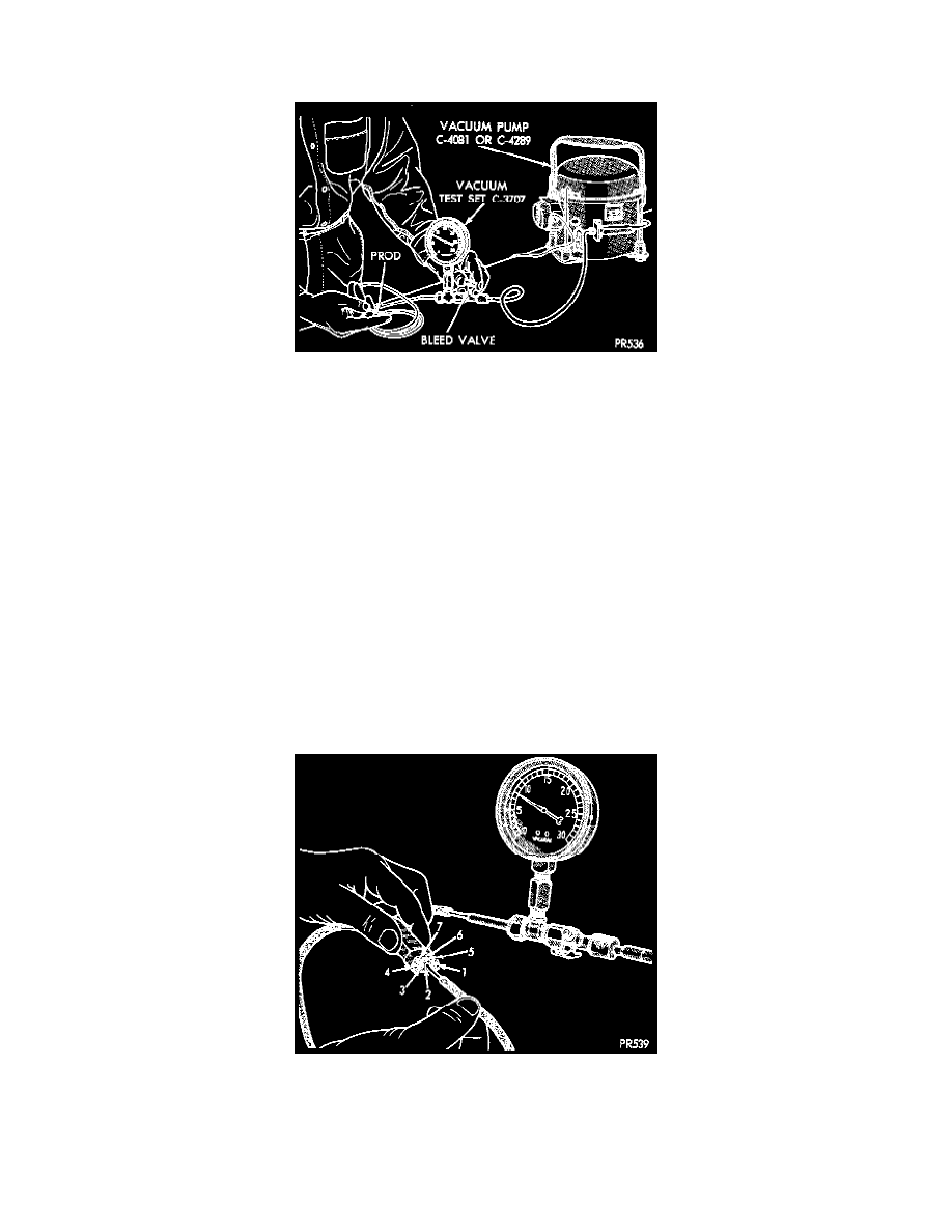
Adjusting Test Bleed Valve
Use an adjustable Vacuum Test Gauge (C -3707) and a suitable vacuum pump to test heater A/C control vacuum. With a finger placed over the end of
test hose, calibrate vacuum control valve on the test gauge to obtain -27 kPa (8 in. Hg.). Release and block the end of the test hose several times to
verily vacuum setting.
VACUUM TESTING THE ONE-WAY CHECK VALVE
1. In the engine compartment, disconnect the Heater-A/C vacuum supply (black) hose. This hose passes through an opening in the dash panel used
for either the heater hoses, or the air conditioning expansion valve (depending on the vehicle model).
2. Remove the vacuum check valve. This valve is located on the (black) vacuum supply hose at either the intake manifold or near the brake power
booster (depending on vehicle model).
3. Connect test vacuum supply hose to the HEATER side of the valve. In this direction the gauge should return to calibrated setting. If valve leaks
vacuum in this direction, valve replacement is necessary.
4. Connect test vacuum supply hose to the ENGINE VACUUM side of the valve. Vacuum should flow through valve.
VACUUM TESTING THE HEATER-A/C CONTROLS NON-ATC SYSTEMS
1. Connect the test vacuum prod to the vehicles (black) vacuum supply hose. Position vacuum test gauge so it can be viewed from the passenger
compartment.
2. Position the heater A/C control mode selector to DEFROST, FLOOR, BI-LEVEL, PANEL, and RECIRC (with A/C). Pause after each selection.
The test gauge should return to the calibrated setting of -27 kPa (8 in. Hg.) after each selection is made. If the gauge cannot achieve the calibrated
setting, a vacuum circuit or component has a leak.
Vacuum Tube Assembly Test
LOCATING VACUUM LEAKS
To locate a vacuum leak, disconnect 7-way vacuum connector behind the instrument panel at the heater A/C control. Connect the calibrated
vacuum hose prod to each port in the vacuum harness connector. The brown, bi-level, vacuum circuit has a metal fiber restrictive device located in
the line. More reaction time is required for the test gauge to return to calibrated setting. After each connection is made, the test gauge should return
to calibrated setting. If all circuits function properly, replace control mode vacuum switch. If not, determine the color of the vacuum circuit that is