
Dynasty L4-153 2.5L SOHC VIN K TBI (1992)
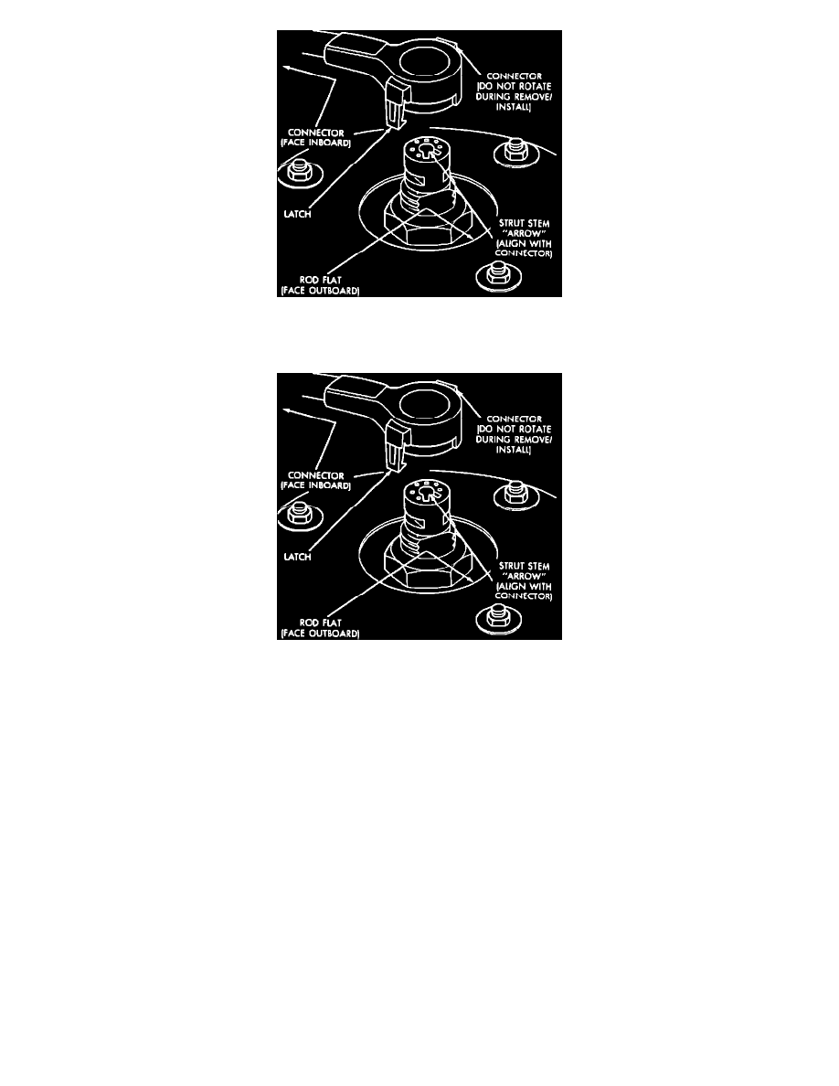
Fig. 8 Variable Strut Damper Electrical Connector
4. Remove cam bolt, knuckle bolt or bolts, washer plate or plates and brake hose to damper bracket attaching screw.
Fig. 8 Variable Strut Damper Electrical Connector
5. On 1990 models with variable damping, disconnect electrical connector from upper strut rod by pinching the two latching arms, then pulling
connector straight off of rod end. Do not rotate connector.
6. On all models, remove strut damper to fender shield attaching nut and washer assemblies.
7. Remove strut damper from vehicle.
INSTALLATION
1. Position strut assembly into fender reinforcement, then install retaining nuts and washers and torque to specification.
2. Position steering knuckle and washer plate to strut, then install cam and through bolts.
3. Install brake hose retainer on damper, then index alignment marks made during removal.
4. Position a four inch or larger C-clamp on steering knuckle and strut, then tighten clamp just enough to eliminate any looseness between strut and
knuckle. Check alignment of marks made during removal. Torque cam bolt nuts to specifications, then advance nuts an additional 1/4 turn.
5. Remove C-clamp, then install wheel and tire assembly. Torque wheel nuts to specification.
6. On 1990 models with variable damping, attach electrical connector to top of strut rod, using caution to align key-way (wire should point toward
vehicle center line). Connector is correctly installed when both latching fingers engage in strut stem.