
Grand Caravan L4-153 2.5L SOHC VIN K TBI (1988)
Wheel Hub: Service and Repair
Permanent Bearings
REMOVAL
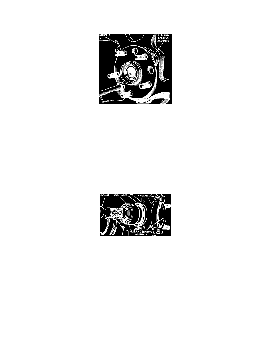
Fig. 15 Removing hub & bearing assembly
1. Remove cotter pin, locknut and spring washer.
2. Loosen hub nut with brakes applied. The hub and drive shaft are splined together through the knuckle (bearing) and retained by the hub
nut.
3. Raise and support vehicle, then remove front wheel and tire assembly.
4. Remove hub nut and washer.
5. Using puller tool No. C-3894-A or equivalent, disconnect tie rod end steering arm.
6. Remove bolt attaching ball joint stud to steering knuckle.
7. Remove caliper guide pins, then the caliper. Support caliper with wire and position aside. Do not hang by brake hose.
8. Remove rotor, then separate ball joint stud from knuckle assembly. Care must be taken not to separate inner CV joint during this procedure.
Do not allow driveshaft to hang by inner CV joint, driveshafts must be supported.
9. Remove four hub and bearing assembly attaching screws from front of steering knuckle as shown.
10. Remove hub and bearing assembly.
INSTALLATION
Fig. 16 Seal installation
1. Install hub and bearing assembly. Tighten bolts in a crossing pattern to specifications.
2. Using oil seal installer tool No. C-4698 or equivalent, install seal into knuckle. Lubricate circumference of seal using a suitable lubricant.
3. Using oil seal installer tool No. C-4698 or equivalent, reverse driving head of tool and install wear sleeve. Lubricate circumference of wear sleeve
using a suitable lubricant.
4. Install driveshaft through hub, then steering knuckle assembly on lower control arm ball joint stud.
5. Install ball joint to steering knuckle clamp bolt, and tighten bolt to specifications.
6. Install tie rod end into steering arm, then tighten bolt to specifications, then install cotter pin.
7. Install rotor, then position caliper over rotor and guide hold-down spring below machined guides on knuckle assembly.
8. Install guide pins and tighten to specifications.
9. Install washer and hub nut, then with brakes applied, tighten nut to specifications.
10. Install spring washer, locknut and cotter pin.