
Grand Caravan L4-153 2.5L SOHC VIN K TBI (1988)
Main Relay (Computer/Fuel System): Testing and Inspection
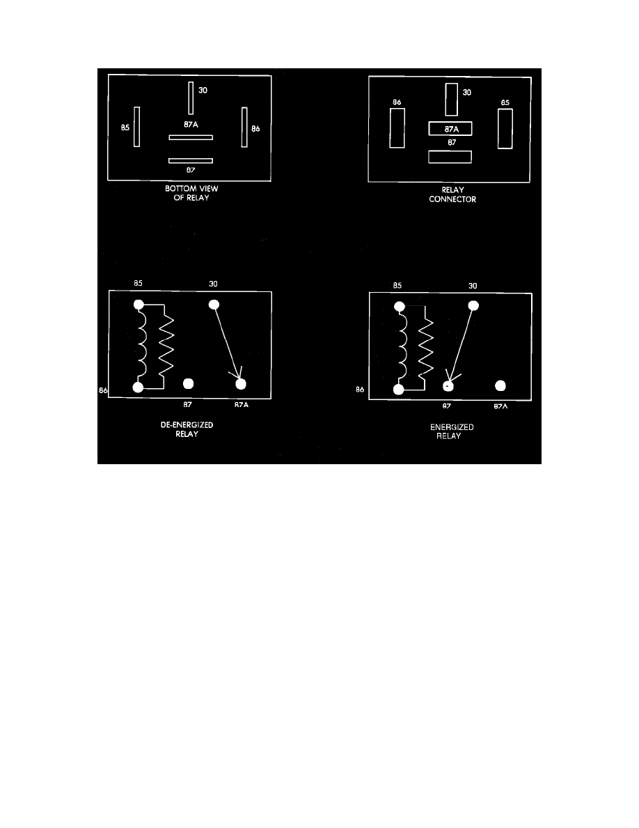
Auto Shutdown (ASD) Relay
Relay Terminal Identification
ASD RELAY TERMINAL IDENTIFICATION
The following is a list of the terminal numbers, with circuit codes, and color codes, and their function:
Circuit No. Terminal No.
Color Code
Description
J1
30
Red
Has battery input voltage supplied through fusible link.
Z1
87
Green/blk.
Connected to J1 circuit (terminal 30) in the energized position, supplies output voltage to fuel pump, O2
sensor, fuel injectors, and coil.
K14
86
Blue/wht.
Connected to the electromagnet, (diode) and the Single Module Engine Controller (SMEC). The SMEC
provides input voltage to relay.
K19
85
Blue/yel.
Connected to the electromagnet (diode) and grounded by the SMEC when distributor signal is present.
N/A
87A
N/A
Not used in these applications.
ASD RELAY TEST
NOTE: The ASD relay operation may be tested with the use of the DRB II scanner or equivalent.
If no scanner is available proceed with the following test.
1.
Connect a voltmeter to the J1 (terminal 30) wire at the ASD connector. Check for battery voltage. If no voltage is present, check fusible links and
supply voltage from the battery. If voltage is present proceed to step 2.
2.
Connect the voltmeter to the Z1 (terminal 87) wire at the ASD connector. Turn the ignition key to the START position and crank the engine. If