
Grand Caravan L4-2.4L DOHC (1996)
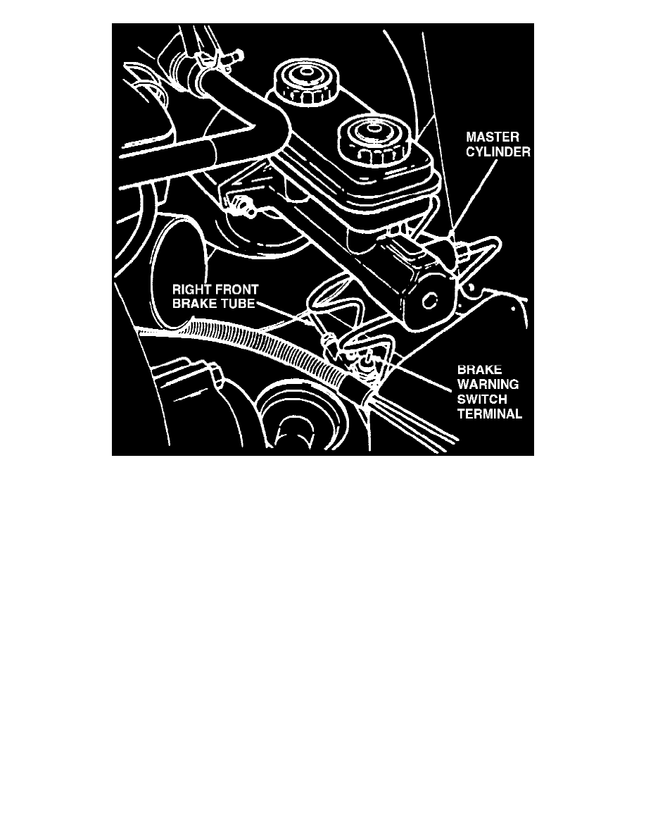
Fig. 3 Master Cylinder & Brake Warning Switch
2. Install gauge and Tee from line pressure set No. C-4007, or equivalent, inline with either master cylinder port to the brake valve assembly.
3. Install second gauge from line pressure set No. C-4007, or equivalent, to either rear brake outlet port between valve assembly and rear brake line.
Bleed both hydraulic circuits and the gauges.
4. Have an assistant exert pressure on the brake pedal to get a reading on the outlet gauge. Outlet test pressure should read 100-200 psi.
5. Inlet pressure should be 500 psi. If not, replace valve and torque mounting bolts to 250 inch lbs.
6. If both gauges read correctly, reinstall actuator assembly, then adjust and road test vehicle.