
Grand Caravan L4-2.4L DOHC (1996)
Hydraulic Control Assembly - Antilock Brakes: Description and Operation
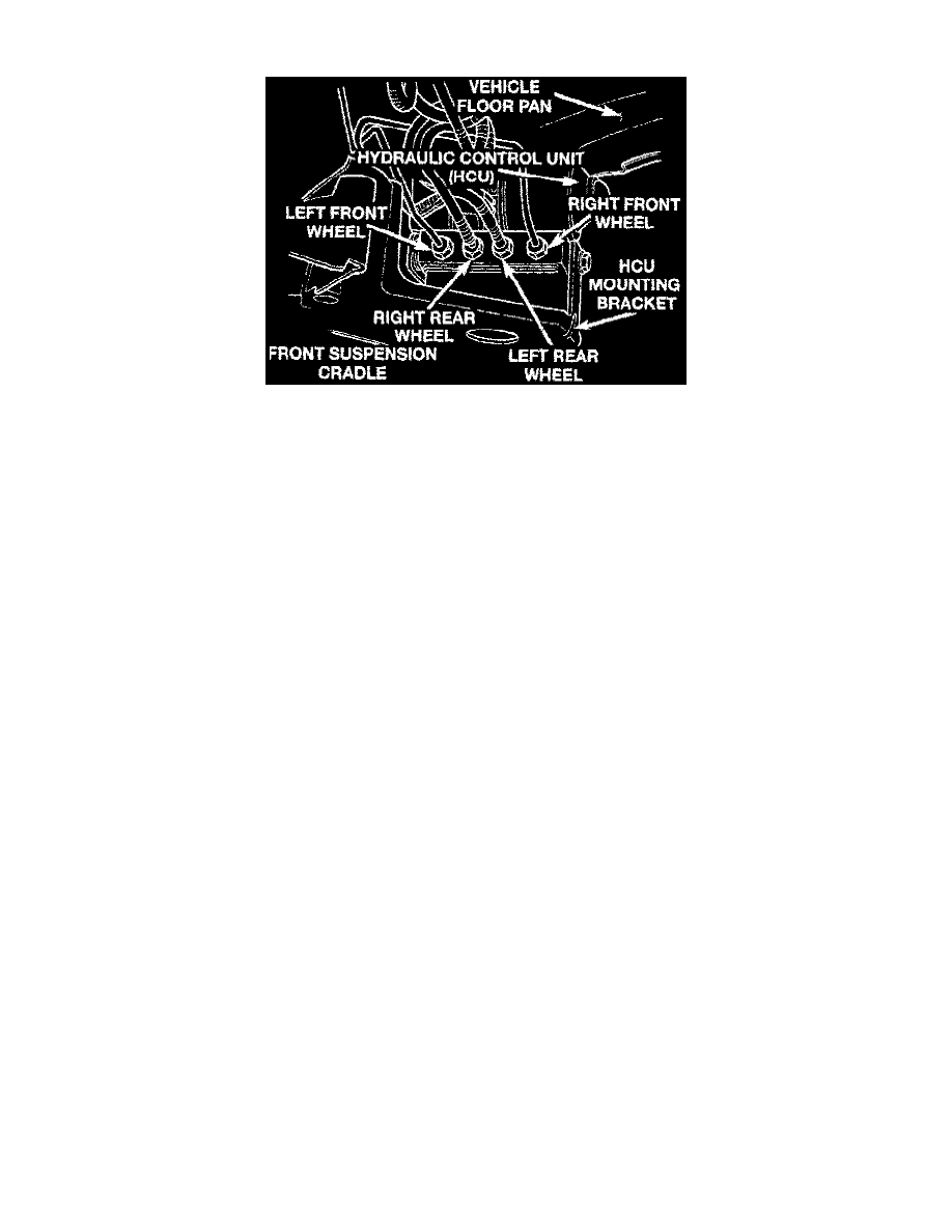
Hydraulic Control Unit.
OPERATION
The Hydraulic Control Unit (HCU), is located on the front suspension crossmember near the lefthand side of the vehicle. With the exception of
its mounting bracket, the HCU is a non-serviceable component. No attempts should be made to service HCU components.
The HCU contains four inlet and four outlet valve solenoids intended to redirect the flow of brake fluid through ABS control components when
ABS operation is required and to allow for normal brake system operation under ordinary conditions. It also contains two fluid accumulators
which temporarily store fluid decayed from wheel circuits during an ABS cycle.
Finally, the unit contains a pump and motor assembly consisting of two pumps driven by a common electric motor. The pumps and motor supply
build pressure to each brake during an ABS stop and are controlled by the Controller Anti-Lock Brake (CAB) via the pump/motor relay. Never
apply voltage to the pump motor ground circuit while testing the HCU; the motor will be damaged. If the pumps or motor require
replacement, the entire HCU must be replaced.
CIRCUIT OPERATION
Power for the solenoids is supplied on circuit B47. This circuit is HOT when the contacts in the ABS system relay are CLOSED.
There are eight solenoids used for controlling the isolation and decay solenoids. Circuits B241 and B243 are used for the left front wheel. Circuits
B246 and B248 are used for the right front wheel. Circuits B237 and B239 are used for the left rear wheel. Circuits B238 and B240 are used for
the right rear wheel.