
Grand Caravan V6-3.3L VIN E Flex Fuel (2007)
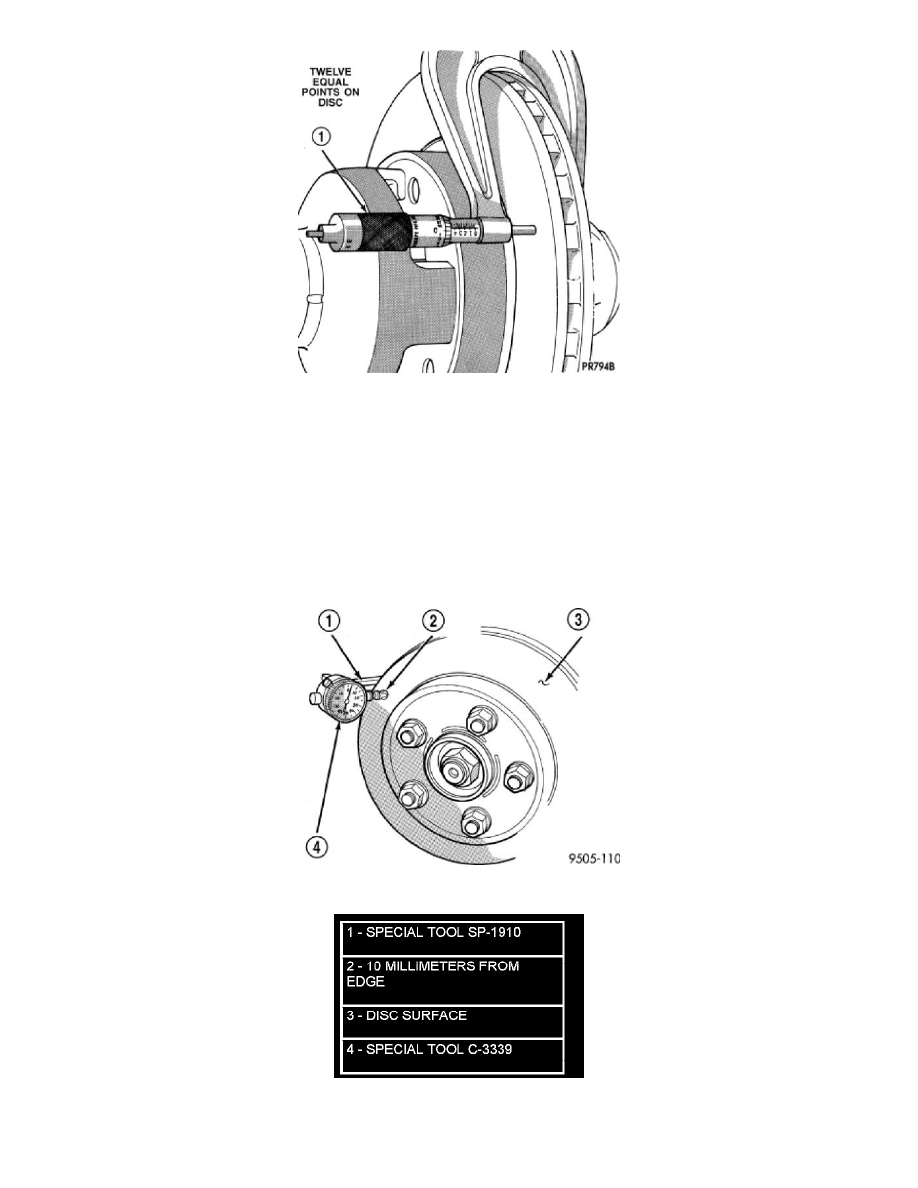
Figure 2 Checking Rotor For Thickness
1 - CALIPER
ROTOR RUNOUT
On-vehicle rotor runout is the combination of the individual runout of the hub face and the runout of the rotor. (The hub and rotor runouts are separable).
To measure rotor runout on the vehicle, first remove the tire and wheel assembly. Reinstall the wheel mounting nuts on the studs, tightening the rotor to
the hub. Mount the Dial Indicator, Special Tool C-3339, with Mounting Adaptor, Special Tool SP-1910 on steering arm. The dial indicator plunger
should contact braking surface of rotor approximately ten millimeters from edge of rotor (Figure 3). Check lateral runout on both sides of the rotor,
marking the low and high spots on both. Runout limits can be found in the specification table in this section. Refer to
BRAKES/HYDRAULIC/MECHANICAL/ROTOR SPECIFICATIONS
Figure 3 Checking Rotor Runout
If runout is in excess of the specification, check the lateral runout of the hub face. Before removing the rotor from the hub, place a chalk mark across
both the rotor and the one wheel stud closest to where the high runout measurement was taken. This way, the original mounting spot of the rotor on the
hub is indexed (Figure 4).