
Grand Caravan V6-3.3L VIN E Flex Fuel (2007)
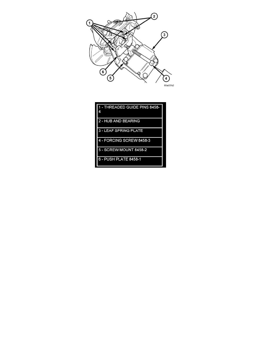
Figure 2 REMOVAL USING SPECIAL TOOL 8458
a. Remove the two outboard spring plate bolts.
b. Thread Threaded Guide Pins into hub and bearing mounting bolt holes.
c. Using the spring plate bolts, install the Screw Mount, Special Tool 8458-2, as shown (Figure 2). Mount the Screw Mount to the spring plate
with the tool number facing the hub and bearing and the beveled edge on the bottom facing the spring, otherwise the Forcing Screw will rub
the spring plate when installed.
d. Place Push Plate, Special Tool 8458-1, on ends of Threaded Guide Pins
e. Place a dab of grease in dimple of Push Plate.
f. Install Forcing Screw, Special Tool 8458-3, through Screw Mount from rear.
g. Tighten the Forcing Screw up against dimple in Push Plate and press hub and bearing out of axle by continuing to tighten screw.
h. Remove the tool.
i. Reinstall the two outboard spring plate bolts. Tighten the bolts to 102 Nm (75 ft. lbs.).
7. Remove the hub/bearing from the rear axle and brake support plate.
Installation
INSTALLATION
1. Install the four hub and bearing to axle mounting bolts into the holes in the flange of the rear axle.
2. Install the rear brake support plate on the four mounting bolts installed in the flange of the rear axle.
3. Align the rear hub and bearing with the four mounting bolts and start mounting bolts into hub and bearing. Tighten the 4 bolts in a crisscross
pattern until the hub and bearing and brake support plate is fully and squarely seated onto flange of rear axle. Tighten the four mounting bolts to
129 Nm (95 ft. lbs.).
NOTE: If equipped with antilock brakes, make sure wheel speed sensor stays clean and dry as it is installed into the hub and bearing cap.
4. If the vehicle is equipped with antilock brakes, perform the following:
a. If metal sensor retaining clip is not in the neutral installed position on hub and bearing cap, install from the bottom, if necessary, and push clip
upward until it snaps into position.
b. Install wheel speed sensor head into rear of hub and bearing aligning index tab with the notch in the top of the mounting hole. Push the sensor
in until it snaps into place on the metal retaining clip.
c. Install secondary (yellow) retaining clip over wheel speed sensor head and engage the tabs on each side (Figure 1).