
Grand Caravan V6-3.3L VIN R (2005)
Diagnostic procedures and DTC numbers are some of the changes you will see which reflect the new combined module technology. The PCM will have
four color coded connectors C1 through C4, (C1-BLK, C2-ORANGE, C3-WHITE, C4-GREEN), each PCM connector will have 38 pins each. Two new
tools are used for probing and repairing the New PCM connectors. A New tool to release the pins from the PCM connectors Miller #3638 is introduced,
you must use the Miller tool #3638 to release the connector pins or harness and connector damage will occur. Also a New tool for probing connectors
Miller #8815 is introduced, you must use the Miller tool #8815 to probe the PCM pins or harness and connector damage will occur. There is also a new
Verification test and module replacement procedure for the PCM.
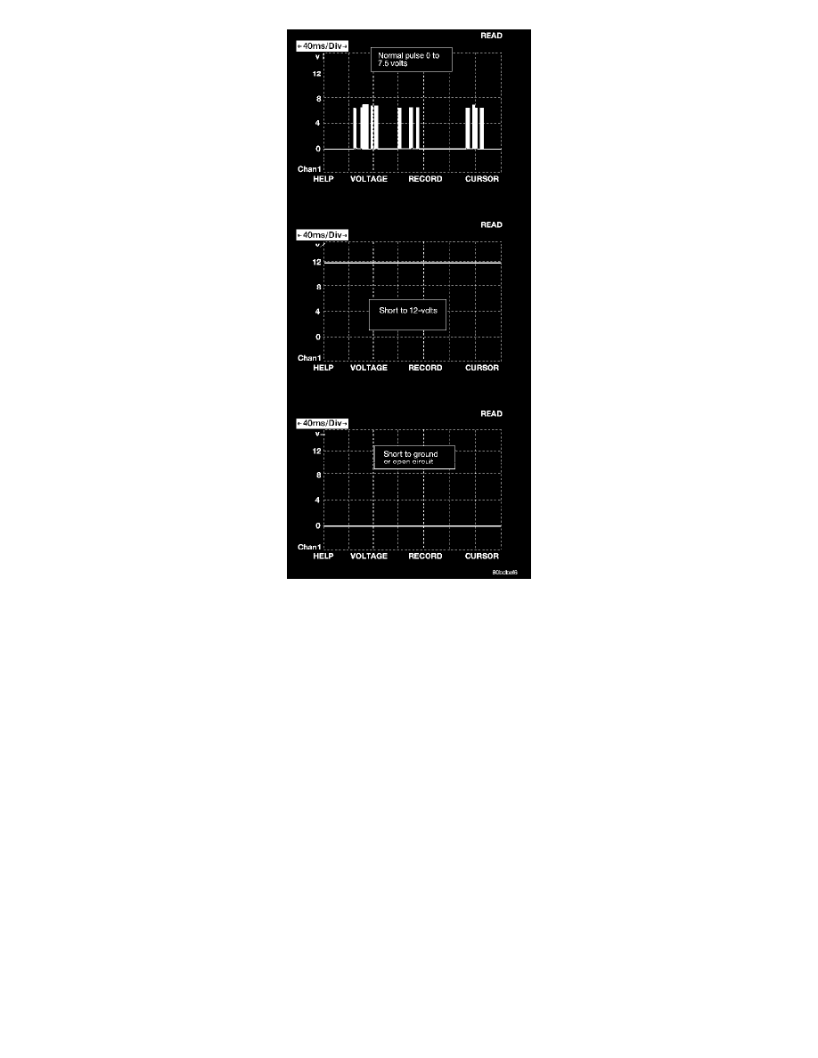
Door Ajar System
The door ajar and liftgate ajar states are used as inputs for the Body Control Module (BCM). The BCM uses these inputs to determine exactly what
position the doors and liftgate are in. The DRBIII(R) will display the state of the door ajar and the liftgate ajar switches in Inputs/Outputs. It's important
to note, that when any door, or the liftgate is closed, the switch state on the DRBIII(R) will show OPEN. When any door, or the liftgate is open the
switch state on the DRBIII(R) will show CLOSED. During diagnosis, if a door or the liftgate is closed and the DRBIII(R) displays the switch state as
CLOSED, it indicates a shorted ajar circuit. If the door or the liftgate is open and the DRBIII(R) displays the switch state as OPEN, it indicates an open
ajar circuit.
Exterior Lighting System
HEADLAMP POWER
The Headlamp Switch is a direct input to the BCM. The BCM sends a BUS message to the FCM informing it of a headlamp switch status change. The
FCM then turns on power to the headlamps through four fuseless circuits. These circuits are electronically controlled and continuously monitored for
malfunctions. Power is supplied to each filament in a separate circuit. For vehicles equipped with daytime running Lamps (DRL), the FCM electronically
steps down the headlamp voltage to provide the desired illumination.
HEADLAMP SWITCH
The Headlamp Switch uses a multiplexed (MUX) circuit to the Body Control Module (BCM). The Headlamp Switch controls the Fog lamp relay, Park
lamps and the Low and High headlamps. The BCM then sends a signal through the PCI Bus line to the FCM as to what state the switch has selected. The
FCM energizes the high side output drivers to turn ON the desired lamps.