
Grand Caravan V6-3.8L VIN L (2007)
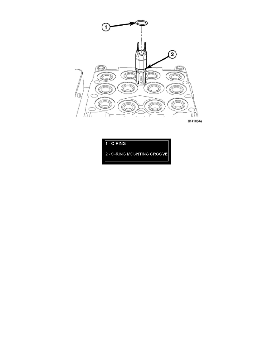
Figure 2 Internal Pump Connector O-Ring
4. Align components and install the ABM on the HCU (Figure 3).
5. If not equipped with traction control, install the three screws attaching the ABM to the HCU (Figure 5). Tighten the mounting screws to 2 Nm (17
in.lbs.) torque.
6. If equipped with traction control, install the four screws attaching the ABM to the HCU (Figure 6). Tighten the mounting screws to 2 Nm (17
in.lbs.) torque.
7. With connector cover completely open (Figure 4), install 47-way wiring connector into socket of the ABM and close cover, locking connector in
place.
8. Install the battery tray.
9. Install the screw securing the coolant filler neck to the battery tray.
10. Reconnect the vacuum hose connector at the tank built into the battery tray.
11. Install the battery and battery shield.
12. Connect the negative cable on the battery negative post.
13. Hook up a scan tool to initialize ABM and check for any faults.
14. Road test vehicle to ensure proper operation of brakes.