
Grand Caravan V6-3.8L VIN L (2007)
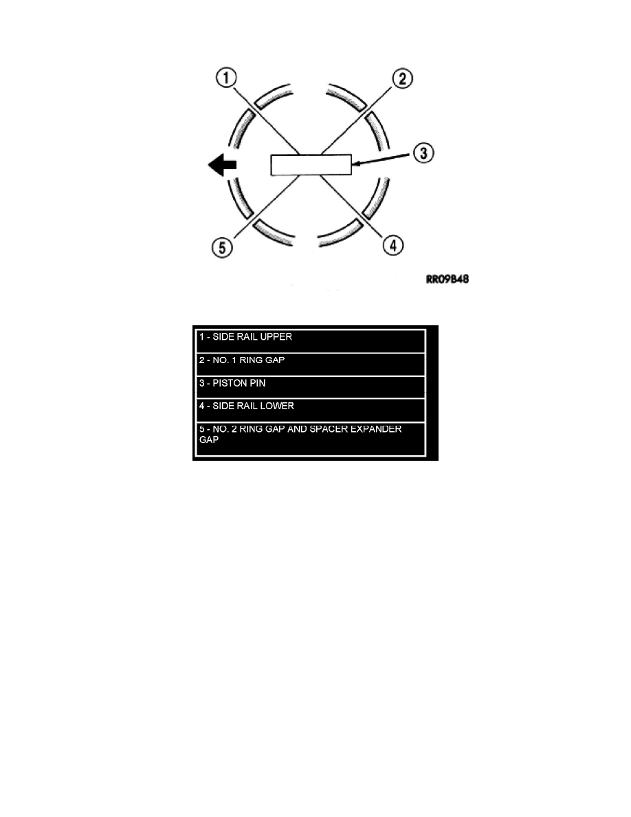
oil ring rail gap (Figure 1).
Figure 1 Piston Ring End Gap Position
2. Before installing the ring compressor, ensure the oil ring expander ends are butted and the rail gaps located as shown in (Figure 1).
3. Lubricate the piston and rings with clean engine oil. Position a ring compressor over the piston and rings, and tighten the compressor (Figure 2).
Be sure position of rings does not change during this operation.
4. Position upper bearing onto connecting rod. Lubricate bearing with oil.
CAUTION: Engines equipped with cracked cap connecting rods must use special tool #8189 to protect the crankshaft from damage
during connecting rod installation (Figure 3).
5. Install connecting rod bolt protectors (rubber hose or equivalent) on the connecting rod bolts (Figure 2), (Figure 3).
6. The pistons are marked with a "F" located near the piston pin. Install piston with this mark positioned to front of engine on both cylinder banks.
The connecting rod oil squirt hole faces the major thrust (right) side of the engine block (Figure 4).
7. Rotate crankshaft until the connecting rod journal is located in the center of the cylinder bore. Insert connecting rod and piston into cylinder bore.
Carefully guide connecting rod over the crankshaft journal (Figure 2).
8. Tap the piston down in cylinder bore, using a hammer handle. At the same time, guide connecting rod into position on connecting rod journal.
9. Install lower bearing shell and connecting rod cap (Figure 2). Install connecting rod cap retaining nuts on cleaned and oiled rod bolts and tighten
to 54 Nm (40 ft. lbs.) PLUS 1/4 turn. Install connecting rod bolts and tighten to 7 Nm (5 ft. lbs) initially. Tighten the bolts an additional 21 Nm
(15 ft. lbs.) and then turn each bolt 90° to final specification.