
Grand Caravan V6-3.8L VIN L (2007)
7. If the vehicle is equipped with traction control, remove the switch wiring from the routing clip attached to the upper shroud (Figure 4).
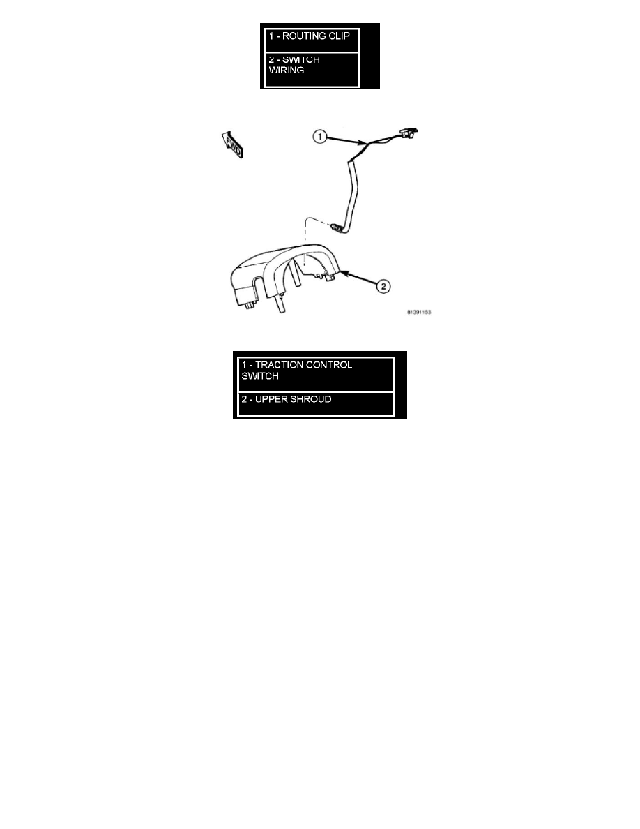
Figure 5 Traction Control Switch Mounting
8. If the vehicle is equipped with traction control, remove the traction control switch from the upper shroud (Figure 5).
9. If the vehicle is equipped with power foldaway mirrors, remove power foldaway switch from upper shroud.
Installation
INSTALLATION
1. If the vehicle is equipped with power foldaway mirrors, install the power foldaway switch in the upper shroud.
2. If vehicle is equipped with traction control, install the traction control switch in the upper shroud (Figure 5).
3. If the vehicle is equipped with traction control, attach the switch wiring to the routing clip attached to the upper shroud (Figure 2).
4. Position the upper shroud on the column (Figure 4).
5. If equipped with traction control, route the switch wiring down around the column. Connect the wiring connector from the column wiring harness
to the traction control switch wiring (attached to upper shroud) (Figure 1).
6. If removed, position the lower shroud on the column (Figure 3). Install the lower shroud mounting screw. Tighten the screw to 2 Nm (17 in. lbs.)
torque.
7. Align the upper shroud with the lower, then snap shrouds together at locking tab locations on both sides of column.
8. Install the two shroud-to-shroud mounting screws (Figure 4). Tighten the screws to 2 Nm (17 in. lbs.) torque.
9. Inspect shroud mating surfaces for excessive gaps and correct as necessary.
10. Check operation of any previously disconnected switches.