
Grand Caravan V6-3.8L VIN L (2007)
9. Remove the hub and bearing assembly from the steering knuckle.
Installation
INSTALLATION
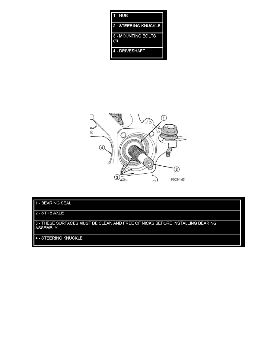
CAUTION: Hub and bearing assembly mounting surfaces on the steering knuckle and stub axle (Figure 1) must be smooth and completely free
of foreign material or nicks prior to installing hub and bearing assembly.
Figure 1 Mounting Surfaces (Typical)
CAUTION: When installing hub and bearing into steering knuckle, be careful not to damage the bearing seal (Figure 1) on the outer C/V joint.
1. Install hub and bearing onto stub axle and into steering knuckle until squarely seated on the face of the steering knuckle.
2. Install the 4 hub and bearing mounting bolts from the rear of the knuckle. Equally tighten all 4 mounting bolts in a criss-cross pattern until
hub/bearing assembly is squarely seated against front of steering knuckle. Tighten mounting bolts to a torque of 65 Nm (45 ft. lbs.)
3. Install the brake rotor on the hub and bearing (Figure 2).
4. Install brake caliper and adapter assembly back over brake rotor and align with mounting holes on steering knuckle (Figure 2). Install the mounting
bolts and tighten to 169 Nm (125 ft. lbs.) torque.
5. Install the hub nut on the end of the stub axle (Figure 3). With aid of a helper applying the brakes to keep the front hub from turning, tighten the
hub nut to Install the mounting bolts and tighten to 244 Nm (180 ft. lbs.) torque.
6. Install wheel and tire assembly on vehicle. Tighten the wheel mounting stud nuts in proper sequence until all nuts are torqued to half specification.
Then repeat the tightening sequence to the full specified torque of 135 Nm (100 ft. lbs.).
7. Lower vehicle to the ground.
8. Check the front wheel alignment toe setting and reset if not within specifications.