
Grand Caravan V6-4.0L (2008)
Power Sliding Door Drive Assembly: Service and Repair
Power Sliding Door Drive Assembly - Installation
INSTALLATION
WARNING: To avoid serious or fatal injury on vehicles equipped with airbags, disable the Supplemental Restraint System (SRS) before
attempting any steering wheel, steering column, airbag, seat belt tensioner, impact sensor, or instrument panel component diagnosis or service.
Disconnect and isolate the battery negative (ground) cable, then wait two minutes for the system capacitor to discharge before performing
further diagnosis or service. This is the only sure way to disable the SRS. Failure to take the proper precautions could result in accidental
airbag deployment.
WARNING: To avoid serious or fatal injury, never strike or drop the side impact sensor, as it can damage the impact sensor or affect its
calibration. The side impact sensor enables the system to deploy the side Supplemental Restraint System (SRS) components. If an impact sensor
is accidentally dropped during service, the sensor must be scrapped and replaced with a new unit. Failure to observe this warning could result
in accidental, incomplete, or improper side SRS component deployment.
NOTE: The service power sliding door drive assembly does not include the Power Sliding Door Control Module (PSDM). The PSDM must be
transferred from the original drive assembly to the new service part. See: Power Sliding Door Module/Service and Repair/Power Sliding Door
Module - Installation for the PSDM installation procedure.
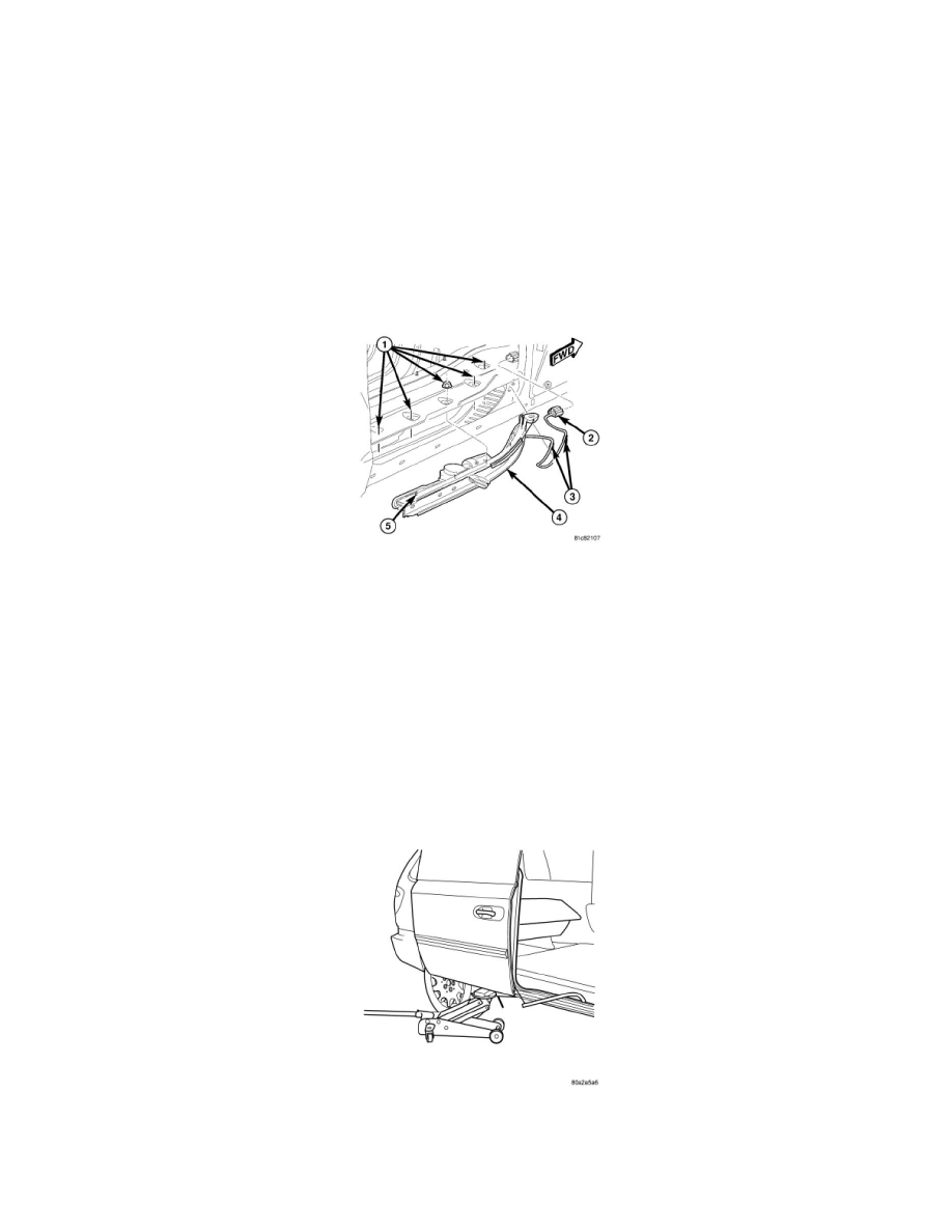
1. Position the power sliding door drive assembly into the vehicle.
a. Insert the drive assembly (4) into the sliding door sill cavity, curved end first by the B-Pillar area.
b. Rotate the straight end of the drive assembly toward the vehicle so that the entire assembly is in the sill cavity.
c. Lift the drive assembly up to insert the studs (5) into the floor pan holes.
d. Install the five power sliding door drive assembly retaining nuts (1) finger tight.
2. Tighten the power sliding door drive assembly retaining nuts (1).
a. Tighten the forward most nut to 9 Nm (80 in. lbs).
b. Tighten the rearward most nut to 9 Nm (80 in. lbs).
c. Tighten the remaining three nuts, front to back to 9 Nm (80 in. lbs).
3. Attach the wiring harness retaining clips to the body (3).
4. Connect the power sliding door drive assembly electrical connector (2) at the front of the B-Pillar.
5. With the door still supported with an appropriate lifting device, roll door forward until lower roller engages into rear of the lower track.
6. Continue rolling the door forward to engage the upper sliding door hinge into the upper channel.