
Grand Caravan V6-4.0L (2008)
Power Sliding Door Switch: Description and Operation
Overhead Console Power Sliding Door Switch
Description
DESCRIPTION
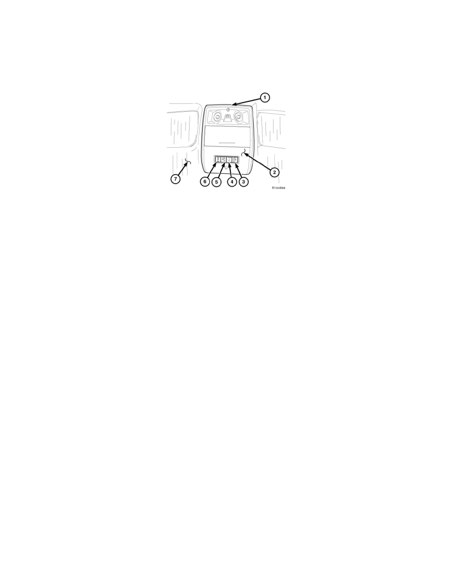
A front overhead console (2) is standard factory-installed equipment on this model. All overhead consoles are equipped with two reading and courtesy
lamps. The front overhead console will be equipped with a four button switch bank on vehicles equipped with power sliding doors and a power liftgate.
The overhead console switch bank buttons perform the following functions:
-
Left power sliding door Open/Close (3)
-
Power liftgate Open/Close (4)
-
Right power sliding door Open/Close (5)
-
Power sliding door Lockout (6)
The individual buttons on the overhead switch bank cannot be serviced separately. If the switch bank is damaged or inoperative the complete switch bank
assembly must be replaced,See: Service and Repair/Overhead Console Power Sliding Door Switch - Removal.
Operation
OPERATION
The overhead power sliding door switch is mounted in the front overhead console of the vehicle. The switch has resistors in parallel of 1.76K ohms,
3.17K ohms and 15K ohms. When pressed, the switch will have a nominal resistance of 1.76K ohms for the right sliding door button, 3.76K ohms for the
left sliding door button and when not pressed, the switch will have a nominal resistance of 15K ohms.
The status of the overhead power sliding door switches is continually monitored by the circuitry within the ElectroMechanical Instrument Cluster
(EMIC) (also known as the Cab Compartment Node/CCN). The instrument cluster receives input messages from the overhead power sliding door
switches over a hardwired connection. Whenever the instrument cluster receives an input from the overhead power sliding door switches it sends a
function command signal to the selected Power Sliding Door Module (PSDM). This message from the cluster to the PSDM is delivered via the
Controller Area Network (CAN) data bus.
When one of the PSDMs receives a command signal it checks the following:
-
PRNDL Status
-
Vehicle Speed Status
-
Ignition Status
-
Vehicle Theft Alarm Armed/Disarmed Status
-
Sliding door Latch Status
-
Sliding Door Full Open Status
-
Ambient Temperature
-
Door Lock Status
-
Sliding Door Window Up/Down Status
If the appropriate conditions exist the PSDM will send a command signal to the selected Rear Door Control Module (RDCM) so the sliding door can be
latched/unlatched as needed. This command signal is sent via the CAN data bus. Once the PSDM senses the latch function it will power the motor on the
power sliding door drive assembly to open/close the sliding door as requested by the overhead power sliding door switches.
The hard wired circuits for the overhead power sliding door switches may be diagnosed using conventional diagnostic tools and procedures. However,