
Grand Caravan AWD V6-3.8L VIN L (2001)
Power Distribution Relay: Testing and Inspection
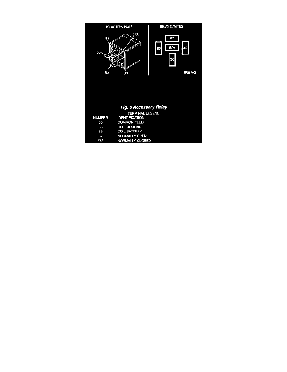
Fig.6 Accessory Relay
The accessory relay (Fig. 6) is located in the intelligent power module, in the engine compartment. For complete circuit diagrams, refer to Wiring
Diagrams.
1. Remove the accessory relay from the intelligent power module. Refer to Accessory Relay in the Removal and Installation for the procedure.
2. A relay in the de-energized position should have continuity between terminals 87A and 30, and no continuity between terminals 87 and 30. If OK,
go to Step 3. If not OK, replace the faulty relay.
3. Resistance between terminals 85 and 86 (electromagnet) should be 75 ± 5 ohms. If OK, go to Step 4. If not OK, replace the faulty relay.
4. Connect a battery to terminals 85 and 86. There should now be continuity between terminals 30 and 87, and no continuity between terminals 87A
and 30. If OK, perform the Relay Circuit Test that follows. If not OK, replace the faulty relay.
Relay Circuit Test
1. The relay common feed terminal cavity (30) of the intelligent power module is connected to battery voltage and should be hot at all times. Check
for battery voltage at the fused B(+) circuit cavity in the intelligent power module receptacle for the accessory relay. If OK, go to Step 2. If not
OK, repair the fused B(+) circuit to the intelligent power module fuse as required.
2. The relay normally closed terminal (87A) is connected to terminal 30 in the de-energized position, but is not used for this application. Go to Step
3.
3. The relay normally open terminal (87) is connected to the common feed terminal (30) in the energized position. This terminal supplies battery
voltage to the fused B(+) fuse in the intelligent power module that feeds the accessories when the relay is energized by the ignition switch. There
should be continuity between the intelligent power module cavity for relay terminal 87 and the fused B(+) fuse in the intelligent power module at
all times. If OK, go to Step 4. If not OK, repair the open fused B(+) circuit to the intelligent power module fuse as required.
4. The coil ground terminal (85) is connected to the electromagnet in the relay. It receives battery feed to energize the accessory relay when the
ignition switch is in the Accessory or ON positions. Turn the ignition switch to the ON position. Check for battery voltage at the fused ignition
switch output (acc/run) circuit cavity for relay terminal 85 in the intelligent power module receptacle for the accessory relay. If OK, go to Step 5.
If not OK, repair the open fused ignition switch output (acc/run) circuit to the ignition switch as required.
5. The coil battery terminal (86) is connected to the electromagnet in the relay. The intelligent power module cavity for this terminal should have
continuity to ground at all times. If not OK, repair the open ground circuit to ground as required.