
Grand Caravan FWD L4-2.4L VIN B (1997)
Cruise Control Switch: Testing and Inspection
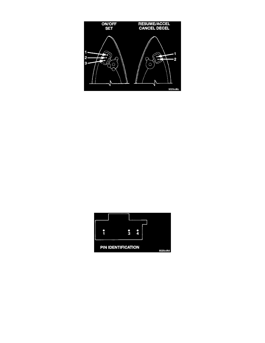
Fig. 5 Speed Control Switch Pins
1. Remove the ON/OFF and SET speed control switch assembly and disconnect the three-way connector.
2. Using an ohmmeter, touch one lead to Pin 1 and the second lead to Pin 3.
-
The meter should read no continuity.
-
Press the ON/OFF button, the ohmmeter should read 0 to 0.5 ohms.
-
Press the SET button, the ohmmeter should read 6,583 to 6,717 ohms.
-
If the resistance does not fall within these values replace switch.
3. Remove the RESUME/CANCEL/DECEL speed control switch assembly and disconnect the two-way connector.
4. Using an ohmmeter, touch one lead to one Pin and the second lead to the other Pin.
-
The meter should read no continuity.
-
Press the RESUME/ACCEL button, the ohmmeter should read 15,246 to 15,554 ohms.
-
Press the CANCEL button, the ohmmeter should read 899 to 919 ohms.
-
Press the DECEL button, the ohmmeter should read 2,910 to 2,970 ohms.
-
If the resistance values do not fall within these specification replace the switch.
5. If the ON indicator does not illuminate check for continuity with a diode checker between Pins 2 (+) and Pin 3 (-) of the ON/OFF and SET switch.
If diode checker is not available use test leads. Using two test leads, connect the first lead to battery voltage and the other end to Pin 2. Connect the
second lead to ground and the other end to Pin 3. The LED should light if not replace the switch. If OK, go to Step 6.
6. If LED OK, but does not light when connected check the speed control dimmer module.
a. Remove top cover shroud to access the turn signal multi-function switch.
b. Check all switch wire connectors for proper connection.
c. The speed control dimmer module is located on the right back side of the turn signal multi-function. Remove the screw attaching the dimmer
module and remove.
Fig. 6 Speed Control Dimmer Module Terminals
d. Using a ohmmeter, check for continuity between Pin 1 and Pin 3 then between Pin 3 and Pin 4. If not OK, replace speed control dimmer
module. If OK, go to Step 7.
7. If steps Step 5 and Step 6 indicate the LED is OK, refer to Diagrams and test the V32 wire circuit out.