
Grand Caravan FWD V6-3.3L VIN 3 Flex Fuel (2002)
Seat Heater Switch: Testing and Inspection
Passenger Heated Seat Switch Test
For complete circuit diagrams, refer to Wiring Diagrams.
WARNING: REFER TO THE RESTRAINTS SECTION OF THIS MANUAL BEFORE ATTEMPTING ANY STEERING WHEEL,
STEERING COLUMN, SEAT OR INSTRUMENT PANEL COMPONENT DIAGNOSIS OR SERVICE. FAILURE TO TAKE THE PROPER
PRECAUTIONS COULD RESULT IN ACCIDENTAL AIRBAG DEPLOYMENT AND POSSIBLE PERSONAL INJURY.
Checking Switch Signal And Wiring At The Module
1. Disconnect and isolate the battery negative cable.
2. Access and disconnect the gray 4-way connector from the heated seat module. Visually inspect wiring terminals for damage that would prevent
positive connection. If not OK, repair or replace the necessary components.
3. Reconnect the negative battery cable and Turn heated seat ON in the LO position. Using an Ohmmeter, check the resistance between cavities 2
and 3 of the gray connector noted above. Resistance should be about 3.5 kiloohms (3500 ohms). If not OK, check resistance directly at switch, as
noted below. If OK, proceed. If NOT OK replace the switch or faulty wiring.
4. Turn heated seat ON in the HI position. Using an Ohmmeter, check the resistance between cavities 2 and 3 of the gray connector noted above.
Resistance should be about 1.4 kiloohms (1400 ohms). If not OK, check resistance directly at switch, as noted below. If OK, proceed. If NOT OK
replace the switch or faulty wiring.
5. With the system ON in the HI position, Check for battery voltage and ground at cavities 4 and 1. If OK, proceed with testing remaining
components. If NOT OK, repair open or wiring short.
Checking Switch Only
1. Disconnect and isolate the battery negative cable. Remove the center bezel from the instrument panel. Check for continuity between the ground
circuit cavity (# 10) of the instrument panel switch bank electrical connector and a good ground. There should be continuity. If OK, go to Step 2.
If not OK, repair the open ground circuit to ground as required.
2. Reconnect the battery negative cable. Turn the ignition switch to the ON position. Check for battery voltage at the fused ignition switch output
(run) circuit cavity of the instrument panel switch bank connector (# 4). If OK, turn the ignition switch to the OFF position, and go to Step 3. If not
OK, repair the open fused ignition switch output (run) circuit as required.
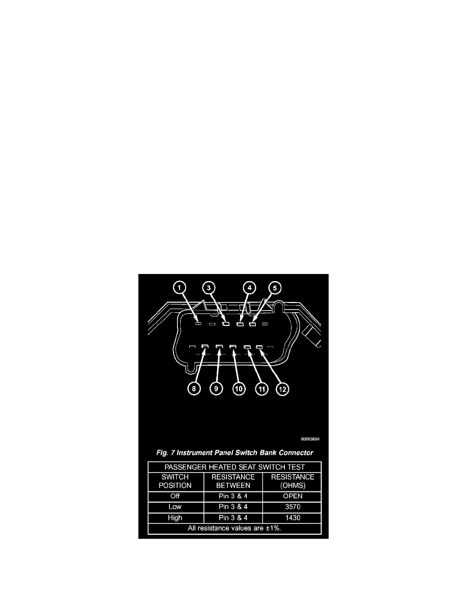
Fig.7 Instrument Panel Switch Bank Connector
3. Test the heated seat switch as shown in the Heated Seat Switch Test chart and the connector pin-out below. If OK, go to Step 4. If not OK, replace
the faulty switch bank assembly.