
Grand Caravan FWD V6-3.3L VIN 3 Flex Fuel (2002)
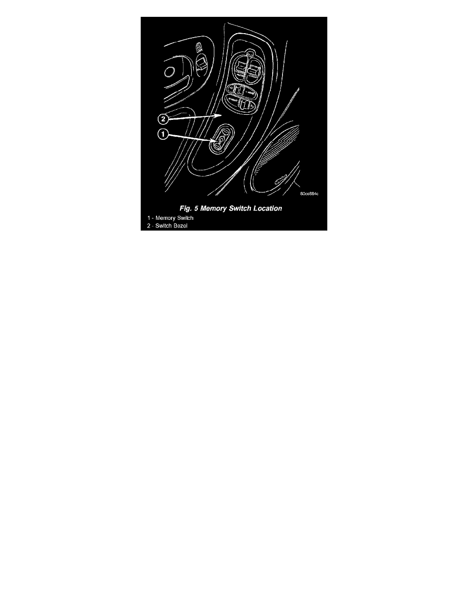
Fig.5 Memory Switch Location
MEMORY SET SWITCH
Vehicles equipped with the memory system have a memory switch mounted to the driver side front door trim panel. This switch is used to set and
recall all of the memory system settings for up to two drivers. The memory switch is a resistor multiplexed unit that is hard wired to the Body
Control Module (BCM). The BCM sends out the memory system set and recall requests to the other electronic modules over the Programmable
Communications Interface (PCI) data bus.
The memory switch cannot be adjusted or repaired and, if faulty or damaged, it must be replaced. For complete circuit diagrams, refer to Wiring
Diagrams.
The memory switch has three momentary switch buttons labeled Set, 1 and 2. The Driver 1 and Driver 2 buttons are back-lit with Light-Emitting
Diodes (LED) for visibility. When the memory set switch is depressed, a resistance value is sent to the Body Control Module via hard wired
connections. When the memory system is in "set" mode a chime will be generated by the body control module.
See the owner's manual in the vehicle glove box for more information on the features, use and operation of the memory switch.
PASSENGER SEAT SWITCH
Vehicles equipped with power seats utilize a tenway power seat switch. This ten-way power seat switch features two knobs ganged together on the
outboard seat cushion side shield.
The switch is secured to the back of the seat cushion side shield with two screws. However, the control knobs for the seat switch unit must be
removed before the seat switch can be removed from the side shield.
The power seat switch cannot be repaired. If one switch is damaged or faulty, the entire power seat switch unit must be replaced.
When a power seat switch control knob or knobs are actuated, a battery feed and a ground path are applied through the switch contacts to the
power seat track or recliner adjuster motor. The selected adjuster motor operates to move the seat track or recliner through its drive unit in the
selected direction until the switch is released, or until the travel limit of the adjuster is reached. When the switch is moved in the opposite
direction, the battery feed and ground path to the motor are reversed through the switch contacts. This causes the adjuster motor to run in the
opposite direction.
No power seat switch should be held applied in any direction after the adjuster has reached its travel limit. The power seat adjuster motors each
contain a self-resetting circuit breaker to protect them from overload. However, consecutive or frequent resetting of the circuit breaker must not be
allowed to continue, or the motor may be damaged. See the owner's manual in the vehicle glove box for more information on the power seat switch
functions and the seat adjusting procedures.