
Grand Caravan FWD V6-3.3L VIN 3 Flex Fuel (2002)
8. Install the primary and secondary brake tubes into their correct port locations on the HCU valve block. Tighten the tube nuts to a torque of 17 Nm
(145 in. lbs.).
CAUTION: When installing the chassis brake tubes on the HCU valve block, they must be located correctly in the valve block to ensure proper
ABS operation.
NOTE: The chassis brake tube attachment locations to the HCU, are marked on the bottom of the CAB.
9. Install the (4) chassis brake tubes into their correct port locations on the HCU valve block as shown. Tighten the tube nuts to a torque of 17 Nm
(145 in. lbs.).
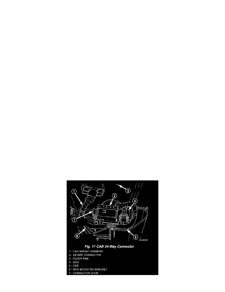
NOTE: Before installing the 24-way connector in the CAB be sure the seal is properly installed in the connector.
10. Install the 24-way connector on the CAB by, first, positioning the 24-way connector in the socket of the CAB and carefully pushing it down as far
as possible. Once connector is fully seated by hand into the CAB socket, push down on connector lock. This will pull the connector into the socket
of the CAB and lock it in the installed position.
11. Install any routing clips on the brake tubes.
12. Remove the brake pedal holder.
13. Install the speed control servo with its mounting nuts.
14. Connect the wiring harness to the speed control servo.
15. Install the battery tray.
16. Install the screw securing the coolant filler neck to the battery tray.
17. Reconnect the vacuum hose connector at the tank built into the battery tray.
18. Install the battery.
19. Install the battery shield.
20. Remove the brake pedal holder.
21. Connect negative cable back on negative post of the battery.
22. Bleed the Base and ABS brake hydraulic systems
23. Road test vehicle to ensure proper operation of the base and antilock brake systems.
RHD
REMOVAL - RHD
NOTE: Before proceeding, Refer to Service Precautions
1. Disconnect the negative (ground) cable from the battery and isolate cable.
2. Using a brake pedal depressor, move and lock the brake pedal to a position past the first inch of pedal travel. This will prevent brake fluid from
draining out of the master cylinder when the brake tubes are removed from the HCU.
3. Raise vehicle.