
Grand Caravan FWD V6-3.3L VIN 3 Flex Fuel (2002)
Hydraulic Control Assembly - Antilock Brakes: Service and Repair
Removal and Installation
LHD
REMOVAL - LHD
1. Disconnect the negative (ground) cable from the battery and isolate cable.
2. Remove the battery shield.
3. Remove the battery.
4. Disconnect the vacuum hose connector at the tank built into the battery tray.
5. Remove the screw securing the engine coolant filler neck to the battery tray.
6. Remove the battery tray.
7. Using a brake pedal depressor, move and lock the brake pedal to a position past the first inch of pedal travel. This will prevent brake fluid from
draining out of the master cylinder once the brake tubes are removed from the HCU.
CAUTION: Do not apply a 12-volt power source to any terminals of the 24-way CAB connector when disconnected.
8. Disconnect the wiring harness connector from the speed control servo.
9. Remove the speed control servo mounting nuts and move the servo out of the way.
10. Disconnect the 24-way connector from the CAB. To disconnect the 24-way connector, grasp the lock on the 24-way connector and pull it as far up
as possible. This will unlock the 24-way connector from the socket on the CAB.
CAUTION: Before removing the brake tubes from the HCU, the HCU must be thoroughly cleaned. This must be done to prevent dirt particles
from falling into the ports of HCU or entering the brake tubes.
11. Thoroughly clean all surfaces of the ICU and brake tube nuts. Use only a solvent such as Mopar Brake Parts Cleaner or equivalent to clean the
ICU.
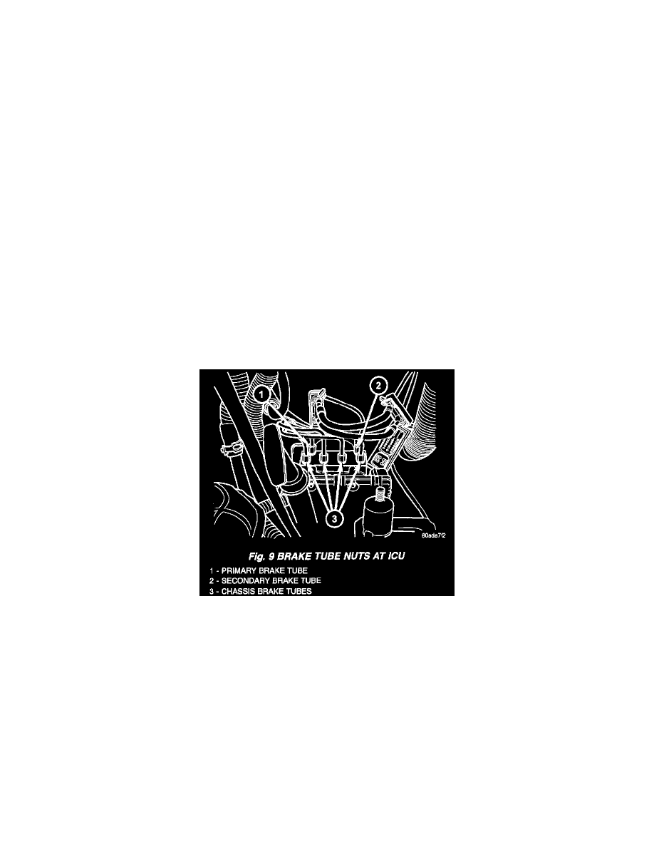
12. Remove the brake tubes (4) from the outlet ports on the HCU.
13. Remove the primary and secondary brake tubes from the inlet ports on the HCU.
14. Center and prop the steering wheel.
15. Remove the silencer panel under the instrument panel, below the steering column.
16. Remove the pinch bolt and disconnect the steering shaft coupling.