
Grand Caravan FWD V6-3.3L VIN 3 Flex Fuel (2002)
7.
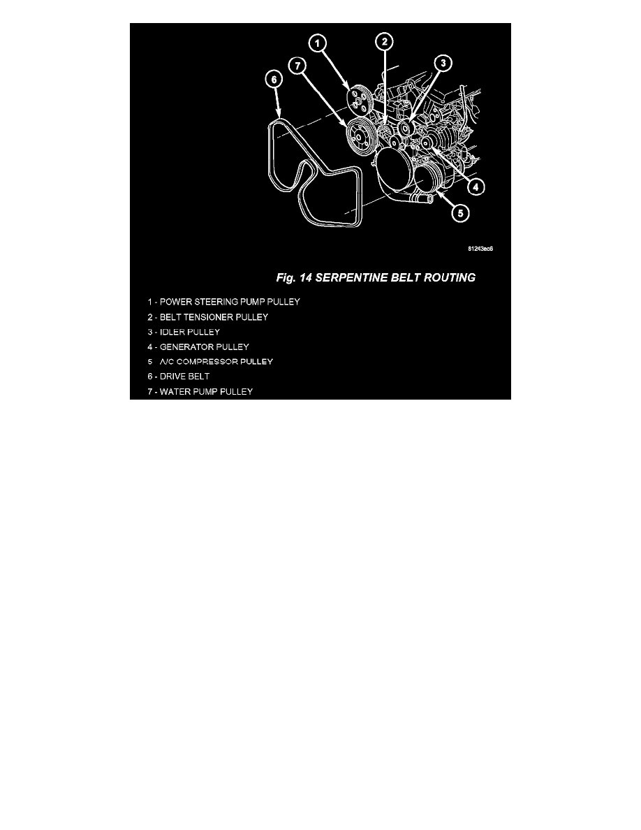
Install the serpentine drive belt (Fig. 14).
8.
Install the right side splash shield.
9.
Vehicles with single A/C system, proceed to next step. Vehicle with dual A/C system, connect the suction lines at the center connection under the
vehicle and install the tie strap (Fig. 5). Tighten the center connection fitting to 23 Nm (17 ft. lbs.).
10.
Lower the vehicle.
11.
RG vehicles proceed to next step. RS vehicles install the new discharge line, p/n 04677492AA.
12.
Connect the discharge line to the compressor. Tighten the discharge line retaining nuts to 23 Nm (17 ft. lbs.).
13.
RG vehicles proceed to step 15. RS vehicles, connect the other end of the discharge line to the condenser. Tighten the discharge line retaining nuts
to 23 Nm (17 ft. lbs.).
14.
Install the right headlamp assembly.
15.
Connect the suction line to the compressor. Tighten the suction line retaining nuts to 23 Nm (17 ft. lbs.).
16.
Vehicles with single A/C system, proceed to next step. Vehicles with dual A/C system, replace the 0-ring on the liquid line and then install the
liquid line and suction line to the expansion valve. Tighten the retaining nut to 23 Nm (17 ft. lbs.).
17.
Add an additional 30 ml (1 oz.) of oil (P/N 82300102) to the center port of the new receiver/drier and install the receiver/drier into the mounting
bracket.
18.
Install new 0-rings onto the liquid line ends that connect to the receiver/drier.
19.
Connect the liquid lines to the receiver/drier ports. Tighten the mounting bolts to 2 Nm (18 in. lbs.).
20.
Vehicles with single A/C system, proceed to next step. Vehicle with dual A/C system, connect the right side wiper module drain hose (Fig. 1).