
Grand Caravan FWD V6-3.3L VIN 3 Flex Fuel (2002)
Compressor Clutch Relay: Description and Operation
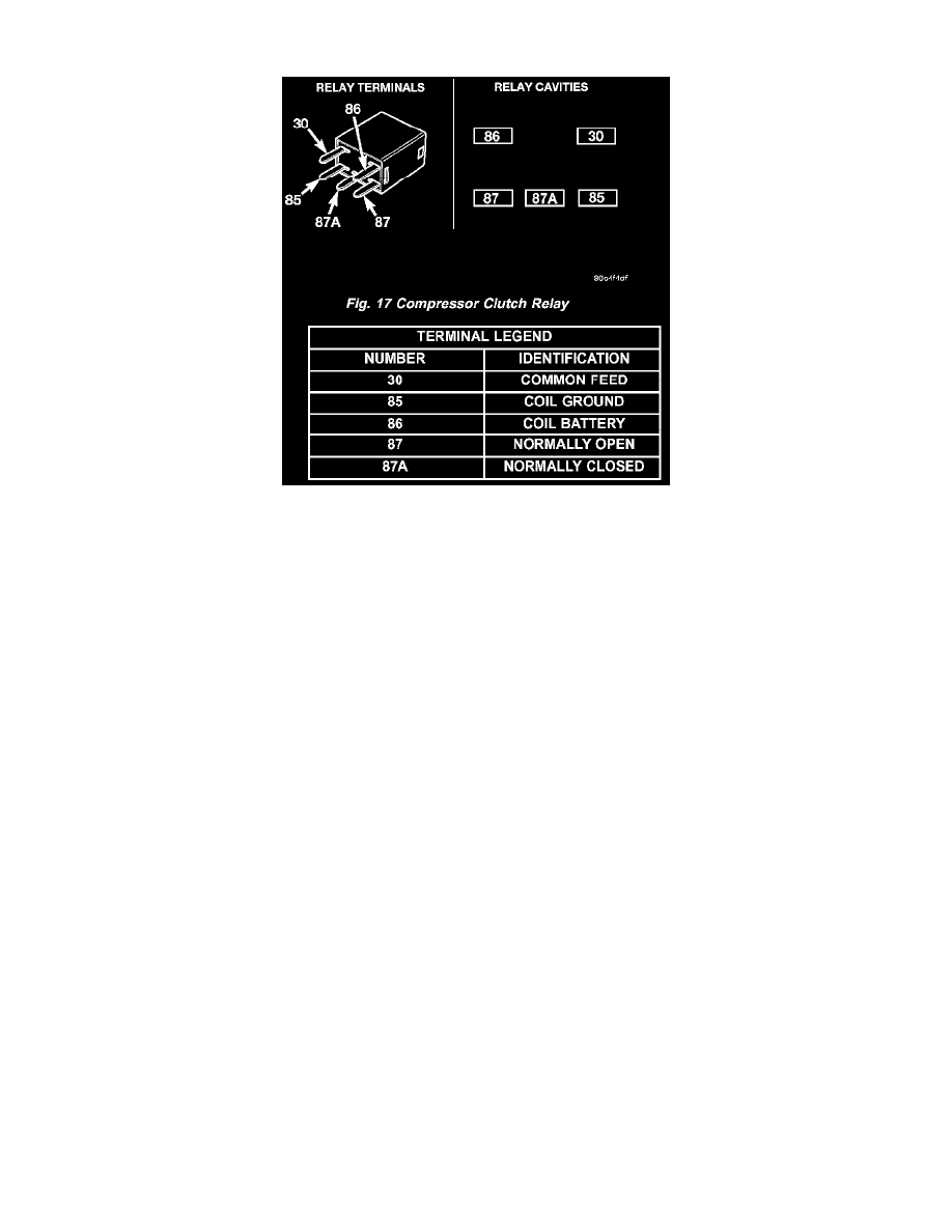
Fig.17 Compressor Clutch Relay
The compressor clutch relay is a International Standards Organization (ISO) micro relay Relays conforming to the ISO specifications have common
physical dimensions, current capacities, terminal patterns, and terminal functions. The ISO micro-relay terminal functions are the same as a conventional
ISO relay. However, the ISO micro-relay terminal pattern (or footprint) is different, the current capacity is lower, and the physical dimensions are
smaller than those of the conventional ISO relay. The compressor clutch relay is located in the Intelligent Power Module (IPM), which is in the engine
compartment near the battery. See the fuse and relay layout map molded into the inner surface of the IPM cover for compressor clutch relay
identification and location.
The black, molded plastic case is the most visible component of the compressor clutch relay Five male spade-type terminals extend from the bottom of
the base to connect the relay to the vehicle electrical system, and the ISO designation for each terminal is molded into the base adjacent to each terminal.
The compressor clutch relay is an electromechanical switch that uses a low current input from the Powertrain Control Module (PCM) to control the high
current output to the compressor clutch electromagnetic coil. The movable common feed contact point is held against the fixed normally closed contact
point by spring pressure. When the relay coil is energized, an electromagnetic field is produced by the coil windings. This electromagnetic field draws
the movable relay contact point away from the fixed normally closed contact point, and holds it against the fixed normally open contact point. When the
relay coil is de-energized, spring pressure returns the movable contact point back against the fixed normally closed contact point. The resistor or diode is
connected in parallel with the relay coil in the relay, and helps to dissipate voltage spikes and electromagnetic interference that can be generated as the
electromagnetic field of the relay coil collapses.
The compressor clutch relay terminals are connected to the vehicle electrical system through a receptacle in the Intelligent Power Module (IPM). The
inputs and outputs of the compressor clutch relay include:
-
The common feed terminal (30) receives a battery current input from a fuse in the IPM through a fused B(+) circuit at all times.
-
The coil ground terminal (85) receives a ground input from the PCM through the compressor clutch relay control circuit only when the PCM
electronically pulls the control circuit to ground.
-
The coil battery terminal (86) receives a battery current input from the PCM through a fused ignition switch output (run-start) circuit only when
the ignition switch is in the ON or Start positions.
-
The normally open terminal (87) provides a battery current output to the compressor clutch coil through the compressor clutch relay output circuit
only when the compressor clutch relay coil is energized.
-
The normally closed terminal (87A) is not connected to any circuit in this application, but provides a battery current output only when the
compressor clutch relay coil is de-energized.
Refer to the appropriate wiring information. The wiring information includes wiring diagrams, proper wire and connector repair procedures, further
details on wire harness routing and retention, as well as pin-out and location views for the various wire harness connectors, splices, and grounds.