
Grand Caravan FWD V6-3.3L VIN 3 Flex Fuel (2002)
Power Distribution Module: Description and Operation
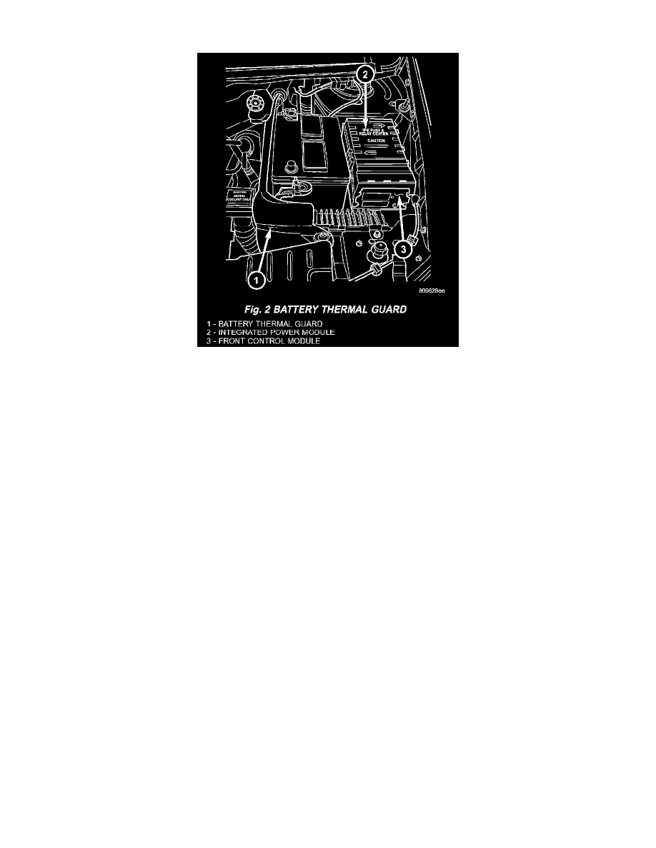
Fig.2 Battery Thermal Guard
INTEGRATED POWER MODULE
The Integrated Power Module (IPM) is a combination of the Power Distribution Center (PDC) and the Front Control Module (FCM). The IPM is
located in the engine compartment, next to the battery on this model (Fig. 2). The power distribution center mates directly with the Front Control
Module (FCM) to form the IPM Fuse and Relay Center. The power distribution center (PDC) is a printed circuit board based module that contains
fuses and relays, while the front control module contains the electronics controlling the IPM and other functions. This IPM connects directly to the
battery positive via a four pin connector. The ground connection is via two other connectors. The IPM provides the primary means of voltage
distribution and protection for the entire vehicle.
The molded plastic IPM housing includes a base and cover. The IPM cover is easily opened or removed for service access by squeezing the two
marked cover latches and has a fuse and relay layout map integral to the inside surface of the cover. This IPM housing base and cover are secured in
place by an IPM mounting bracket. This mounting bracket is designed to allow the IPM to rotate counter-clockwise once the locking tab is
disengaged. The IPM mounting bracket is secured in place by bolts threaded into the left front wheel house.
Replaceable components of the IPM assembly are broken down into the following components: the Power Distribution Center (PDC) (without fuses or
relays), the IPM cover, the Front Control Module (FCM), the IPM mounting bracket, IPM bracket retaining clips and the IPM assembly which
includes the power distribution center, the cover and FCM.
Refer to the Front Control Module in the Electronic Control Module for information on the FCM.
All of the current from the battery and the generator output enters the Integrated Power Module (IPM) via a four-pin connector on the bottom of the
module. The IPM cover is unlatched and opened or removed to access the fuses or relays. Internal connections of all of the power distribution center
circuits is accomplished by a combination of bus bars and a printed circuit board. Refer to the Wiring for complete IPM circuit schematics.