
Grand Caravan FWD V6-3.3L VIN 3 Flex Fuel (2002)
The bus messages are transmitted at a rate averaging 10800 bits per second. Since there is only voltage present when the modules transmit and the
message length is only about 500 milliseconds, it is ineffective to try and measure the bus activity with a conventional voltmeter. The preferred
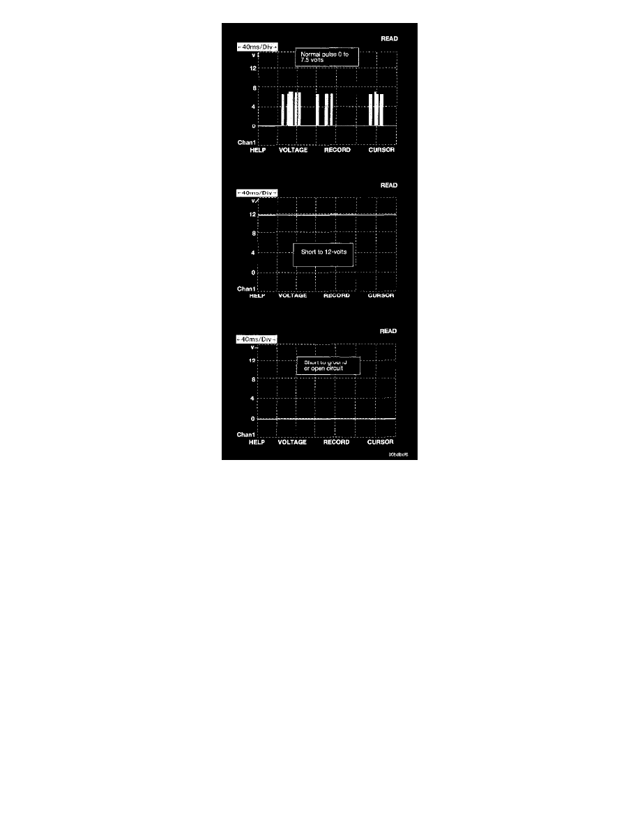
method is to use the DRBIII lab scope. The 12 v square wave selection on the 20-volt scale provides a good view of the bus activity. Voltage on the
bus should pulse between zero and about 7 1/2 volts. Refer to the following figure for some typical displays.
The PCI Bus failure modes are broken down into two categories. Complete PCI Bus Communication Failure and individual module no response.
Causes of a complete PCI Bus Communication Failure include a short to ground or battery on the PCI circuit. Individual module no response can be
caused by an open PCI circuit at the module, or an open battery or ground circuit to the affected module.
Symptoms of a complete PCI Bus Communication Failure would include but are not limited to:
-
All gauges on the MIC stay at zero
-
All telltales on MIC illuminate
-
MIC backlighting at full intensity
-
Dashed lines in the overhead console ambient temperature display
-
No response received from any module on the PCI bus (except the PCM/ECM)
-
No start (if equipped with Sentry Key Immobilizer)
Symptoms of Individual module failure could include any one or more of the above. The difference would be that at least one or more modules would
respond to the DRBIII(R).
Diagnosis starts with symptom identification. If a complete PCI Bus Communication Failure is suspected, begin by identifying which modules the
vehicle is equipped with and then attempt to get a response from the modules with the DRBIII(R). If any modules are responding, the failure is not
related to the total bus, but can be caused by one or more modules PCI circuit or power supply and ground circuits. The DRBIII(R) may display "BUS
+/- SIGNAL OPEN" or "NO RESPONSE" to indicate a communication problem. These same messages will be displayed if the vehicle is not
equipped with that particular module. The CCD error message is a default message used by the DRBIII(R) and in no way indicates whether or not the
PCI bus is operational. The message is only an indication that a module is either not responding or the vehicle is not equipped.
NOTE: For 2003 model year, some vehicles will integrate the Transmission Control Module and Powertrain Control Module into a single control