
Grand Caravan FWD V6-3.3L VIN 3 Flex Fuel (2002)
3. Disconnect the electrical connector.
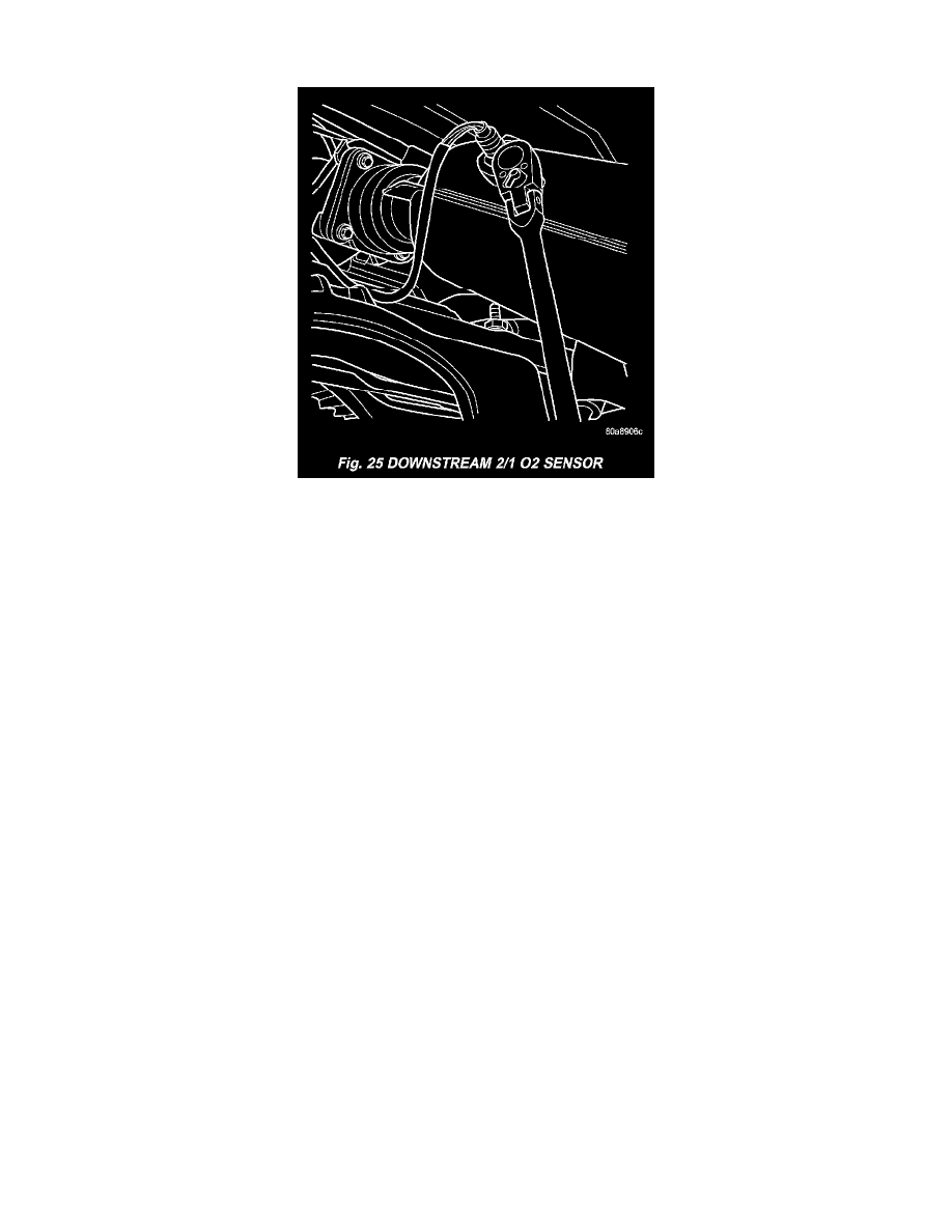
Fig. 25 Downstream 2/1 O2 Sensor
4. Use a socket such as the Snap-On(R) YA8875 or equivalent to remove the sensor.
5. When the sensor is removed, the threads must be cleaned with an 18 mm X 1.5 + 6E tap. If using the original sensor, coat the threads with Loctite
771-64 anti-seize compound or equivalent.
INSTALLATION
Upstream 1/1
The engines uses two heated oxygen sensors.
1. After removing the sensor, the exhaust manifold threads must be cleaned with an 18 mm X 1.5 + 6E tap. If reusing the original sensor, coat the
sensor threads with an anti-seize compound such as Loctite 771-64 or equivalent. New sensors have compound on the threads and do not require
an additional coating.
2. Install sensor and tighten to 27 Nm (20 ft. lbs.).
3. Connect the electrical connector for the O(2) sensor and install onto bracket.
4. Connect the electrical connector for the speed control servo.
5. Install the speed control servo and bracket.
6. Connect the speed control vacuum harness to servo.
7. Install the battery tray.
8. Install battery.
Downstream 2/1
The O(2)S is located on the side of the catalytic converter.
Threads of new oxygen sensors are factory coated with anti-seize compound to aid in removal. DO NOT add any additional anti-seize compound to
the threads of a new oxygen sensor.
1. Install sensor and tighten to 27 Nm (20 ft. lbs.).
2. Connect the electrical connector.
3. Lower vehicle.
4. Install the negative battery cable.