
Grand Caravan FWD V6-3.3L VIN 3 Flex Fuel (2002)
15. Disconnect both tilt mechanism springs from their mounting posts on the tilt housing (Fig. 28), then move them to the side out of the way (Fig.
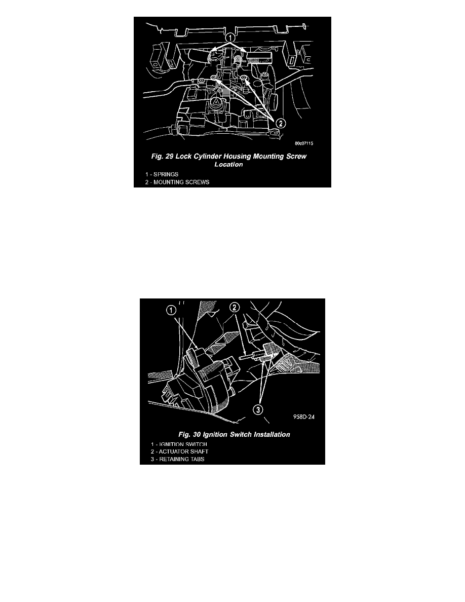
29).
16. While supporting the lock cylinder housing, remove both mounting screws securing the lock cylinder housing to the column (Fig. 29).
17. Remove the lock cylinder housing from the bottom of the steering column.
INSTALLATION
1. Install the lock cylinder housing in the bottom of the steering column lining up the mounting holes.
2. Install the self-tapping lock cylinder housing mounting screws through the top of the column into the housing (Fig. 29). Tighten the two mounting
screws to a torque of 11 Nm (100 inch lbs.).
3. Connect both tilt mechanism springs back onto their mounting posts making sure the spring hooks engage the grooves in the posts (Fig. 28).
4. Ensure that the ignition switch and the actuator shaft in the lock cylinder housing are in the ON position.
5. Carefully install the ignition switch over the actuator shaft (Fig. 30). The switch will snap over the retaining tabs on the housing.
6. Install the ignition switch mounting screw (Fig. 26).
7. Install the key cylinder halo lamp on the lock cylinder housing.
8. Install the vehicle wiring harness connector onto the key cylinder halo lamp (Fig. 25).
9. Install the key cylinder (with key in it turned to the ON position) by sliding it straight into the lock cylinder housing aligning the retaining tab on
the key cylinder with the hole in the lock cylinder housing.
10. Turn the key to the OFF position and remove the key.
11. Connect the shifter/ignition interlock link to the lever on the lock cylinder housing by aligning the retaining tab on the lever with the ramp on the
link (Fig. 23), then pushing the two together.
12. Install the metal cover in place below the shifter/ignition interlock linkage using the two screws (Fig. 22).
13. Install the steering column fixed shroud on the steering column (Fig. 21) using its 2 mounting screws.
14. Install the trim bezel on the instrument panel above the steering column. The trim bezel is mounted to the instrument panel using 2 screws (one on