
Grand Caravan FWD V6-3.8L VIN L (2001)
WARNING: THE PASSENGER AIRBAG MODULE CONTAINS ARGON GAS PRESSURIZED TO 17236.89 Kpa (2500 PSI). DO
NOT ATTEMPT TO DISMANTLE AN AIRBAG MODULE OR TAMPER WITH ITS INFLATOR. DO NOT PUNCTURE,
INCINERATE, OR BRING INTO CONTACT WITH ELECTRICITY. DO NOT STORE AT TEMPERATURE EXCEEDING 93 °C
(200 °F). REPLACE AIRBAG SYSTEM COMPONENTS ONLY WITH PARTS SPECIFIED IN THE MOPAR PARTS CATALOG.
SUBSTITUTE PARTS MAY APPEAR INTERCHANGEABLE, BUT INTERNAL DIFFERENCES MAY RESULT IN INFERIOR
OCCUPANT PROTECTION. THE FASTENERS, SCREWS, AND BOLTS ORIGINALLY USED FOR THE AIRBAG SYSTEM
COMPONENTS HAVE SPECIAL COATINGS AND ARE SPECIFICALLY DESIGNED FOR THE AIRBAG SYSTEM. THEY MUST
NEVER BE REPLACED WITH ANY SUBSTITUTES. ANY TIME A NEW FASTENER IS NEEDED, REPLACE IT WITH THE
CORRECT FASTENERS PROVIDED IN THE SERVICE PACKAGE OR SPECIFIED IN THE MOPAR PARTS CATALOG.
CAUTION: DEPLOYED FRONT AIR BAGS MAY OR MAY NOT HAVE LIVE PYROTECHNIC MATERIAL WITHIN THE AIR BAG
INFLATOR. DO NOT DISPOSE OF 2001 MOPAR YEAR DRIVER AND PASSENGER AIRBAGS UNLESS YOU ARE SURE OF
COMPLETE DEPLOYMENT. PLEASE REFER TO THE HAZARDOUS SUBSTANCE CONTROL SYSTEM FOR PROPER DISPOSAL.
DISPOSE OF DEPLOYED AIR BAGS IN A MANNER CONSISTENT WITH STATE, PROVINCIAL, LOCAL, AND FEDERAL
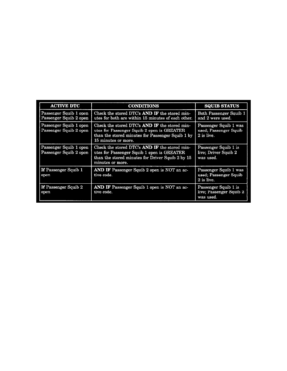
REGULATIONS. USE THE FOLLOWING TABLE TO IDENTIFY THE STATUS OF THE AIRBAG SQUIB.
Airbag Squib Status
1. Using a DRBIII(R) read Airbag DTC's If the following active codes are present:
If neither of the following codes is an active code:
ACTIVE DTC...................................................................................................................................................................................SQUIB STATUS
Passenger squib 1 open ....................................................................................................................................................................Status of Airbag is
Passenger squib 2 open ..................................................................................................................................................................................Unknown.
Seat Belt Tensioner (SBT)
The driver and passenger seat belt (buckle) tensioners are mounted to the inboard side of the front seats. The seat belt buckle and seat belt switch
are connected directly to the seat belt tensioner cable. At the onset of an impact event the ORC uses the seat belt tensioner to rapidly retract the
seat belt buckles. With the slack removed, the occupant's forward motion in an impact will be reduced as will the likelihood of contacting interior
components. The seat belt tensioner cannot be removed, the occupant's forward motion in an impact will be reduced as will the likelihood of
contacting repaired, if damaged or defective it must be replaced. The ORC continuously monitors the resistance of the seat belt tensioner circuits
an open or shorted conditions.
Seat Belt Switches (SBS)
The hall-effect driver and front passenger seat belt switches provide the seat belt status, buckled or unbuckled, via hardwired inputs to the ORC.
The ORC uses seat belt switch inputs to determine the appropriate level of airbag deployment. If the seat belt switches are damaged or defective
the seat belt tensioner must be replaced. The ORC continuously monitors the seat belt switch circuits for an open or shorted conditions.
Side Impact Airbag Control Module (SIACM)
Supplemental driver and front passenger seat airbags provide side impact protection for the front seat occupants. Each side airbag has it own side
impact airbag control module (SIACM) to provide independent impact sensing and deployment. SIACM are located on the left and right B post
just above the seat belt retractor. One, same part number, side impact airbag control module (SIACM) is used on both side of the vehicle.
However, for proper PCI bus operation each SIACM must have a unique module identification. To provide the unique module identification for
both, left and right, the SIACM software looks for a ground on cavity # 5 of the SIACM connector. If cavity # 5 is grounded the SIACM
communicates as a left SIACM otherwise it communicates as a right SIACM. The SIACM performs self diagnostics and circuit tests to determine