
Intrepid V6-2.7L VIN R (2003)
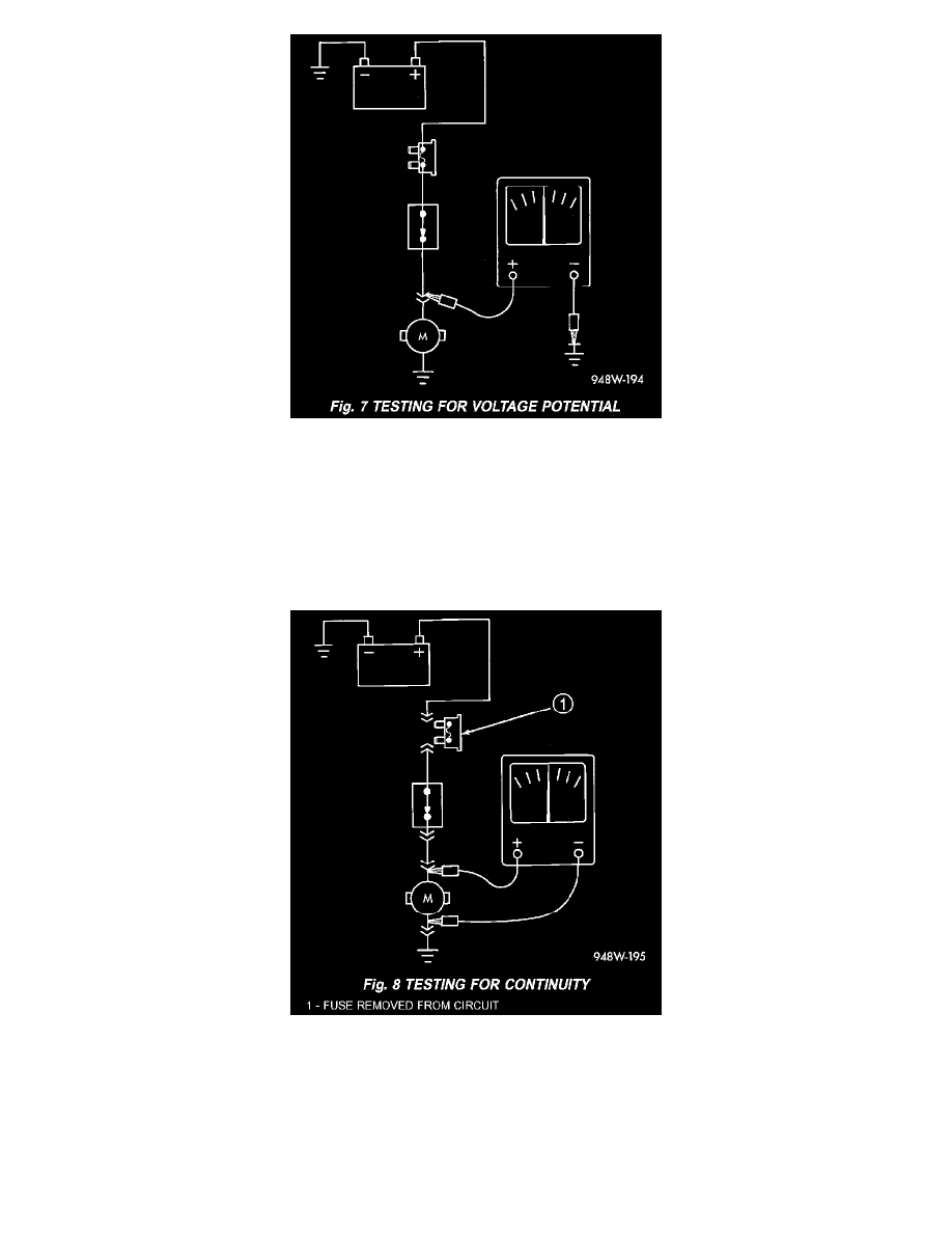
Fig.7 Testing For Voltage Potential
STANDARD PROCEDURE - TESTING FOR VOLTAGE POTENTIAL
1. Connect the ground lead of a voltmeter to a known good ground (Fig. 7).
2. Connect the other lead of the voltmeter to the selected test point. The vehicle ignition may need to be turned ON to check voltage. Refer to the
appropriate test procedure.
STANDARD PROCEDURE - TESTING FOR CONTINUITY
1. Remove the fuse for the circuit being checked or, disconnect the battery.
Fig.8 Testing For Continuity
2. Connect one lead of the ohmmeter to one side of the circuit being tested (Fig. 8).
3. Connect the other lead to the other end of the circuit being tested. Low or no resistance means good continuity.
STANDARD PROCEDURE - TESTING FOR A SHORT TO GROUND
1. Remove the fuse and disconnect all items involved with the fuse.
2. Connect a test light or a voltmeter across the terminals of the fuse.
3. Starting at the fuse block, wiggle the wiring harness about 6 - 8 inches apart and watch the voltmeter/test lamp.