
Intrepid V6-2.7L VIN R (2003)
4.
Remove the four (4) PCM mounting bracket screws and then remove the PCM and mounting bracket assembly (Figure 3).
5.
Remove the three (3) PCM bolts, then remove the PCM and discard it.
6.
Install the new PCM onto the mounting bracket. Tighten the mounting bolts to 105 in-lbs (11.8 Nm).
7.
Install the PCM and bracket assembly (Figure 3). Tighten the mounting bolts to 95 in-lbs (10.7 N.m).
8.
Connect the four (4) PCM electrical connectors (Figure 3).
9.
Attach the wiring harness clips to the PCM bracket.
10.
Connect the negative battery cable.
11.
Continue with Section E - PCM/Vehicle Data Set-up.
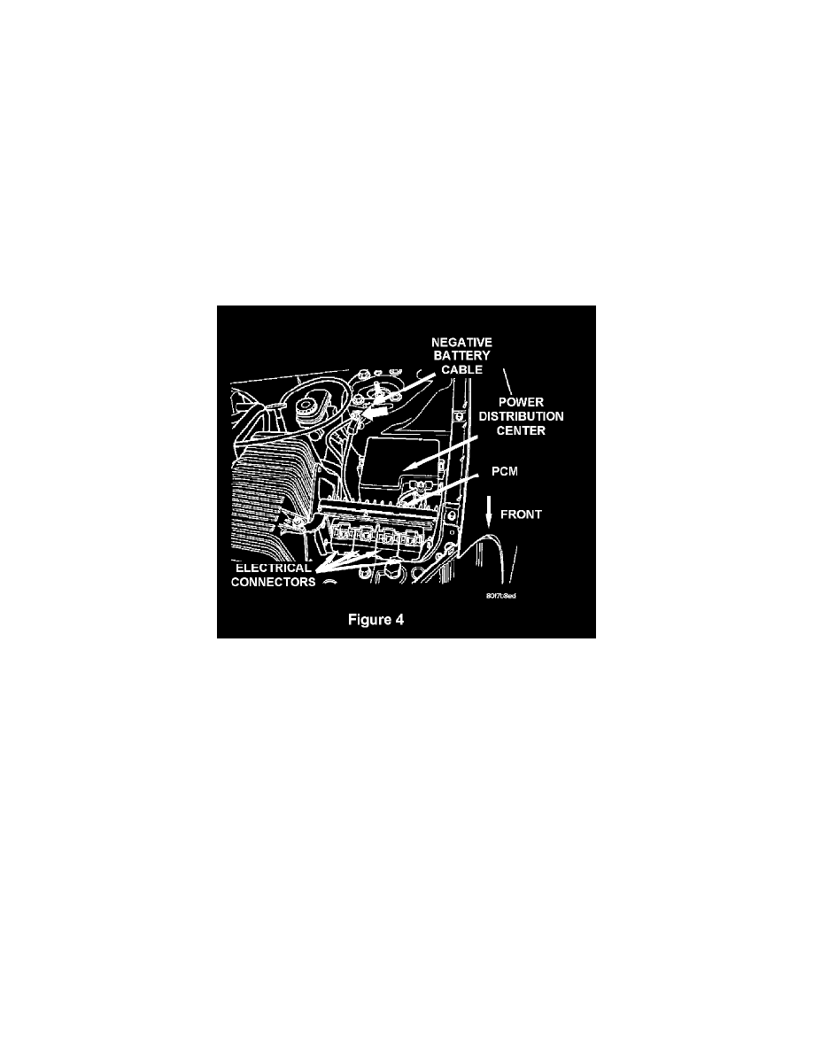
D. Replace PCM - JR Vehicles
1.
Disconnect the negative battery cable (Figure 4).
NOTE:
To enhance customer satisfaction, remember to reset the clock when you have completed the service procedure.
2.
Disconnect the four (4) PCM electrical connectors and set the wiring harness aside (Figure 4).
3.
Remove the two (2) PCM bracket fasteners and then remove the PCM and bracket assembly (Figure 4).
4.
Remove the three (3) PCM bolts, then remove the PCM and discard it.
5.
Install the new PCM on the bracket. Tighten the mounting bolts to 35 in-lbs (4 N.m).
6.
Install the PCM and bracket assembly (Figure 4). Tighten the fasteners to 35 in-lbs (4 N.m).
7.
Connect the four (4) PCM electrical connectors.
8.
Connect the negative battery cable.
9.
Continue with Section E - PCM/Vehicle Data Set-up.
E. PCM/Vehicle Data Set-Up
1.
Connect the DRB III(R) to the data link connector located under the instrument panel. Turn the ignition key to the "ON" position.
2.
With the ignition switch in the "ON" position, determine if the vehicle is equipped with a SKIM module by using the DRB III and selecting from