
Intrepid V6-201 3.3L (1995)
Manifold Pressure/Vacuum Sensor: Description and Operation
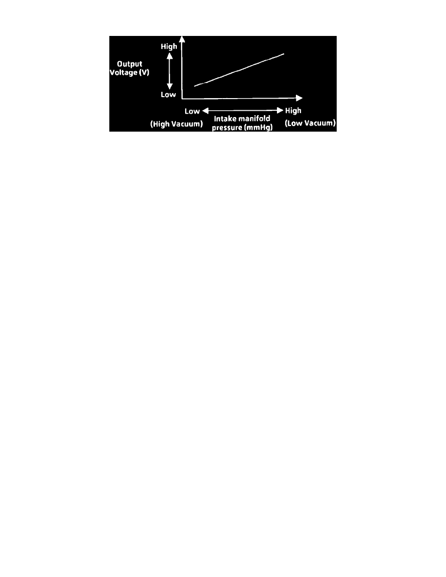
MAP Sensor Output Characteristic
PURPOSE
The Manifold Absolute Pressure (MAP) sensor is used to monitor intake manifold pressure (engine load). It sends voltage signals to the
Powertrain Control Module (PCM) that represent the engines varying load conditions.
THEORY/OPERATION
PCM supplies 5 volt sensor reference voltage. The sensor, connected to manifold vacuum at throttle body, converts intake manifold pressure into
voltage.
Changes in manifold absolute pressure are sensed by a silicon crystal in the MAP sensor. This crystal changes the resistance of the sensor
depending upon the manifold absolute pressure acting upon it, and the change in resistance affects the amount of voltage that the sensor allows to
flow back to the PCM.
Manifold absolute pressure and voltage to PCM are directly proportional (manifold absolute pressure increases, low vacuum, voltage to PCM
increases and vice versa).
Sensor resistance and manifold absolute pressure are inversely proportional (as manifold absolute pressure increases, (low vacuum), sensor
resistance decreases and vice versa).
TYPICAL READINGS
Sensor output voltage range is 0.5 to 4.5 volts.
Output voltages between 0.5 and 1.5 volts indicate a high vacuum (low pressure) situation, such as idle or deceleration.
Output voltages between 1.5 and 3.0 volts indicate a medium level of vacuum (pressure) such as a cruise or slight acceleration condition.
Output voltages between 3.0 and 4.5 volts indicate a low vacuum (high pressure) situation such as hard acceleration or a mechanical failure.
Any reading of 0 volts or over 4.5 volts indicates a problem.
CIRCUIT OPERATION
From the Powertrain Control Module (PCM), circuit K6 supplies 5 Volts to the Manifold Absolute Pressure (MAP) sensor. Circuit K6 connects
to cavity 6 of the PCM connector.
Circuit K1 delivers the MAP signal to the PCM. Circuit K1 connects to cavity 1 of the PCM connector.
The PCM provides a ground path for the MAP signal (circuit K1) through circuit K4. Circuit K4 connects to cavity 4 of the PCM connector.