
Intrepid V6-215 3.5L (1995)
Oxygen Sensor: Description and Operation
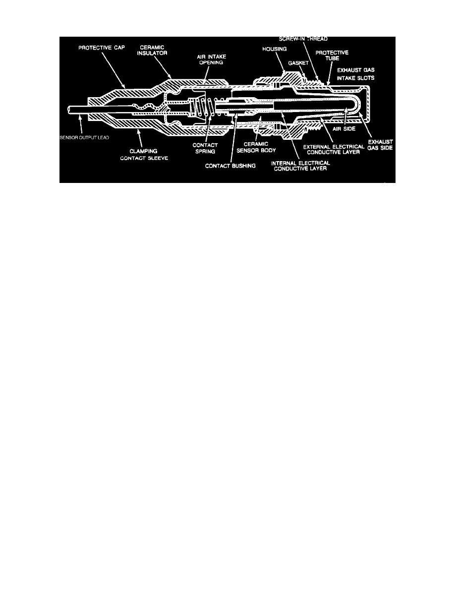
O2 Sensor Cutaway View (Typical)
PURPOSE
This vehicle uses two oxygen sensors. The Powertrain Control Module (PCM) uses these signals to fine tune air/fuel mixture for each cylinder
bank. This is done by varying injector pulse width (on time).
OPERATION
The oxygen sensor is a voltage generating device. A voltage signal (0-1 volt) is generated by comparing the difference in oxygen content between
the exhaust gases and outside air. The higher the difference (rich mixture, low exhaust oxygen content) the higher the voltage generated by the
oxygen sensor. Smaller differences (lean mixture, high exhaust oxygen content) result in a lower voltage being generated.
The oxygen sensor has a heating element that maintains proper oxygen sensor operating temperature at all times. This process allows the vehicle to
enter closed loop at an earlier time and to remain in closed loop during the remainder of the operating cycle. The oxygen sensor heating element
receives voltage from the fuel pump relay.
During CLOSED LOOP operation, the PCM monitors the signals it receives from the oxygen sensor, and other sensors, and uses these signals to
adjust the injector pulse width according to the current driving condition.
During OPEN LOOP operation, the PCM ignores the oxygen sensor's signals, and other sensor's signals, and adjusts injector pulse widths
according to preprogrammed specifications in the PCM.
CIRCUIT OPERATION
Power for the heated oxygen sensors is supplied on circuit F18. This circuit is protected by a 10 Amp fuse located in cavity 20 of the junction
block. Power for the fuse is supplied on circuit A21 from the ignition switch. Circuits A21 and F18 are HOT in the START and RUN position
only.
Power for the A21 circuit is supplied on circuit A1 from the Power Distribution Center (PDC). The A1 circuit is protected by a 20 Amp fuse
located in cavity A.
Circuit K41 delivers the signal from the left heated oxygen sensor to the Powertrain Control Module (PCM). Circuit K41 connects to cavity 41 of
the PCM connector.
Circuit K141 delivers the signal from the right heated oxygen sensor to the PCM. Circuit K141 connects to cavity 49 of the PCM connector.
The PCM provides a ground for the left and right heated oxygen sensor signals (circuits K41 and K141) through circuit K4. Circuit K4 connects to
cavity 4 of the PCM connector.
Circuit Z1 provides the ground path for the heater circuits in the sensors. This ground terminates at the engine ground located at the rear of the
right cylinder head.