
Intrepid V6-3.2L VIN J (1998)
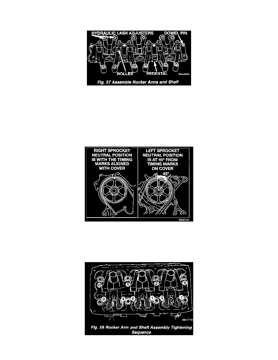
NOTE: The notches on the rocker shafts face up. Notches on the right cylinder bank face towards rear of engine. Notches on left cylinder bank
face toward front of engine.
Figure 57-Assemble Rocker Arms And Shaft
2. Install dowel pins. Dowel pins pass through the pedestal into the exhaust rocker shafts. Dowel pins should be pressed in until they bottom-out
against the rocker shaft in the pedestal.
CAUTION: Inspect all lash adjuster plastic retaining caps for proper retention before installation.
INSTALLATION
NOTE: Rocker arm and shaft assembly can be installed either prior to or after cylinder head installation.
Figure 58-Camshaft Sprockets Neutral Position
1. Rotate camshafts to the position shown in. With the camshafts in these positions the lobes are in a neutral position (no load to the valve). This will
allow the rocker arm shaft assembly to be tightened into position with little or no valve spring load on it.
2. Install the rocker arm and shaft assembly making sure that the identification marks face toward the front of engine for left head and toward the rear
of the engine for right head.
Figure 59 Rocker Arm And Shaft Assembly Tightening Sequence