
Intrepid V6-3.5L VIN K (2003)
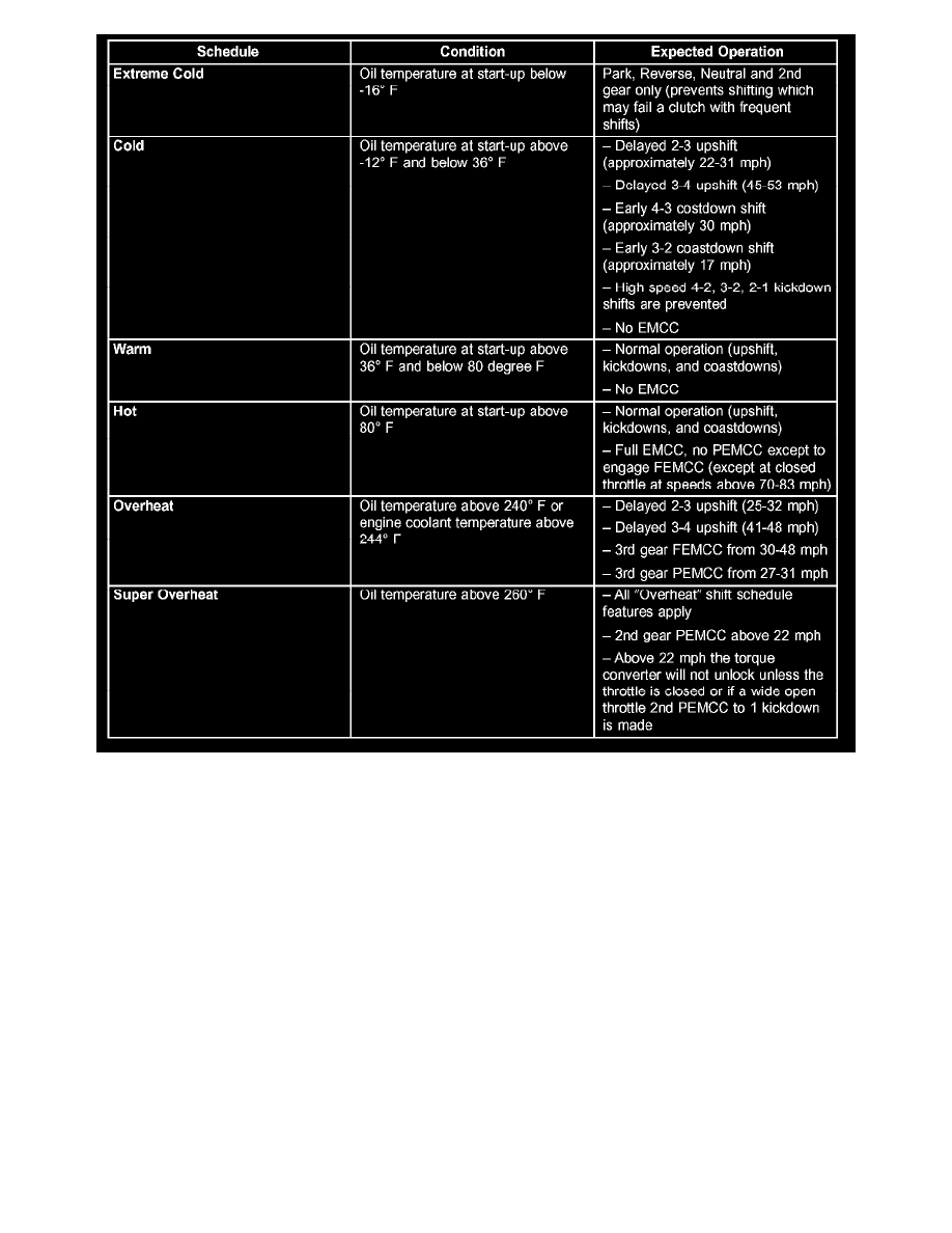
As driving conditions change, the PCM appropriately adjusts the shift schedule. Refer to the chart to determine the appropriate operation expected,
depending on driving conditions.
DATA BUS COMMUNICATION RECEIVE - PCM INPUT
The PCM uses the SCI communication bus to perform engine diagnostics and flash operation. The transmission side of the PCM uses the SCI
communications bus to the flash new software. However, diagnostics is performed via the vehicles J1850 bus for the transmission side of the PCM
SENSOR RETURN - PCM INPUT
The sensor return circuit provides a low electrical noise ground reference for all of the systems sensors. The sensor return circuit connects to
internal ground circuits within the Powertrain Control Module (PCM).
SCI RECEIVE - PCM INPUT
SCI Receive is the serial data communication receive circuit for the DRB scan tool. The Powertrain Control Module (PCM) receives data from the
DRB through the SCI Receive circuit.
IGNITION SENSE - PCM INPUT
The ignition sense input informs the Powertrain Control Module (PCM) that the ignition switch is in the crank or run position.
PCM GROUND
Ground is provided through multiple pins of the PCM connector. There five different ground pins. There are engine power grounds and trans
power grounds.
The power grounds are used to control the ground side of any relay, solenoid, ignition coil or injector.