
Intrepid V6-3.5L VIN K (2003)
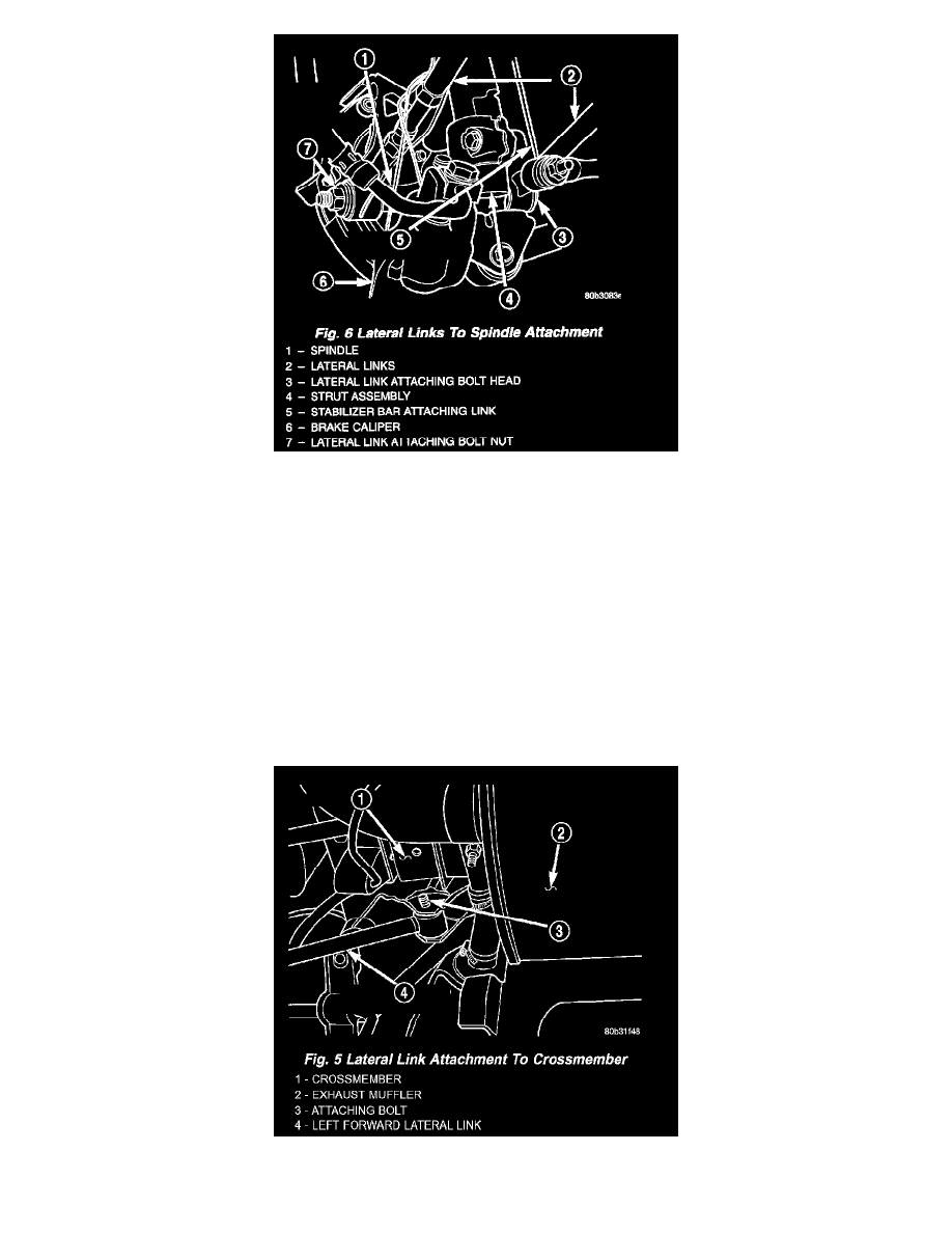
8. Install the lateral links on the spindle. Install, but DO NOT fully tighten the attaching bolt and nut at this time.
CAUTION: Tightening the lateral link attaching bolt at this point will cause the bushing to contort when the vehicle is at curb riding height, thus
contributing to premature failure of the lateral link bushings.
9. Install rear wheel and tire assembly on vehicle.
10. Tighten the wheel mounting stud nuts in proper sequence until all nuts are torqued to half specification. Then repeat the tightening sequence to the
full specified torque of 129 Nm (95 ft. lbs.).
11. Lower vehicle to the ground.
12. Tighten lateral arm to crossmember attaching bolt 95 Nm (70 ft. lbs.).
13. Tighten lateral arm to spindle attaching bolt 135 Nm (100 ft. lbs.).
14. Check and reset rear wheel toe to specifications if required.
LEFT REAR AND BOTH RIGHT LATERAL LINKS
1. Attach the lateral link to crossmember. Rear lateral link attachment bolts should be installed from the rear and point forward. Forward lateral link
attachment bolts should be installed from the front and point rearward.
CAUTION: The bolts attaching the forward lateral links to the crossmember must be installed with the bolts pointing rearward to prevent damage
to the fuel tank and or fuel tubes. Also, the left rear lateral arm attaching bolt to the crossmember is to be installed pointing forward to prevent