
Intrepid V6-3.5L VIN V (2002)
-
Diagnostic capabilities (with DRB III scan tool)
The automatic shut down (ASD) and fuel pump relays are mounted externally, but turned ON and OFF by the powertrain control module.
The camshaft and crankshaft signals are sent to the powertrain control module. If the PCM does not receive both signals within approximately two
second of engine cranking, it deactivates the ASD and fuel pump relays. When these relays are deactivated, power is shut off to the fuel injectors,
ignition coils, fuel pump and the heating element in each oxygen sensor.
The PCM contains a voltage converter that changes battery voltage to a regulated 85.0 volts. The 5.0 volts power the camshaft position sensor,
crankshaft position sensor, vehicle speed sensor, engine coolant temperature sensor, intake air temperature sensor, manifold absolute pressure
sensor, and throttle position sensor.
The PCM engine control strategy prevents reduced idle speeds until after the engine operates for 320 km (200 miles). If the PCM is replaced after
320 km (200 miles) of usage, update the mileage in new PCM. Use the DRB scan tool to change the mileage in the PCM. Refer to the appropriate
Powertrain Diagnostic and the DRB scan tool.
TRANSMISSION CONTROL - CLUTCH VOLUME INDEX (CVI)
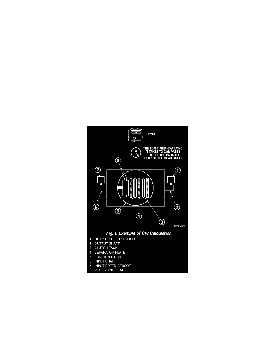
An important function of the PCM is to monitor Clutch Volume Index (CVI). CVIs represent the volume of fluid needed to compress a clutch
pack.
The PCM monitors gear ratio changes by monitoring the Input and Output Speed Sensors. The Input, or Turbine Speed Sensor sends an electrical
signal to the PCM that represents input shaft rpm. The Output Speed Sensor provides the PCM with output shaft speed information.
Fig. 6 Example Of CVI Calculation
By comparing the two inputs, the PCM can determine transaxle gear position. This is important to the CVI calculation because the PCM
determines CVIs by monitoring how long it takes for a gear change to occur.
Gear ratios can be determined by using the DRB Scan Tool and reading the Input/Output Speed Sensor values in the "Monitors" display. Gear
ratio can be obtained by dividing the Input Speed Sensor value by the Output Speed Sensor value.
For example, if the input shaft is rotating at 1000 rpm and the output shaft is rotating at 500 rpm, then the PCM can determine that the gear ratio
is 2:1. In direct drive (3rd gear), the gear ratio changes to 1:1. The gear ratio changes as clutches are applied and released. By monitoring the
length of time it takes for the gear ratio to change following a shift request, the PCM can determine the volume of fluid used to apply or release a
friction element.