
Journey FWD V6-3.5L (2009)
1. Disconnect the battery.
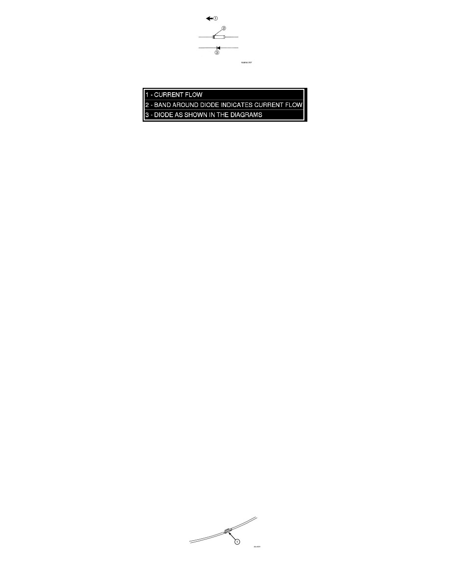
2. Locate the diode in the harness, and remove the protective covering.
3. Remove the diode from the harness, pay attention to the current flow direction (1) (2) (3).
Installation
INSTALLATION
1. Remove the insulation from the wires in the harness. Only remove enough insulation to solder in the new diode.
2. Install the new diode in the harness, making sure current flow is correct. If necessary, refer to the appropriate wiring diagram for current flow.
3. Solder the connection together using rosin core type solder only. Do not use acid core solder.
4. Tape the diode to the harness using electrical tape. Make sure the diode is completely sealed from the elements.
5. Re-connect the battery and test affected systems.
Removal
REMOVAL
1. Follow steps for removing terminals described in the connector removal section.
2. Cut the wire 6 inches from the back of the connector.
Installation
INSTALLATION
1. Select a wire from the terminal repair kit that best matches the color and gage of the wire being repaired.
2. Cut the repair wire to the proper length and remove one-half (1/2) inch of insulation.
3. Splice the repair wire to the wire harness (see wire splicing procedure).
4. Insert the repaired wire into the connector.
5. Install the connector locking wedge, if required, and reconnect the connector to its mating half/component.
6. Re-tape the wire harness starting at 1-1/2 inches behind the connector and 2 inches past the repair.
7. Connect battery and test all affected systems.
Wire Splicing
WIRE SPLICING
When splicing a wire, it is important that the correct gage be used as shown in the wiring diagrams.