
Journey FWD V6-3.5L (2009)
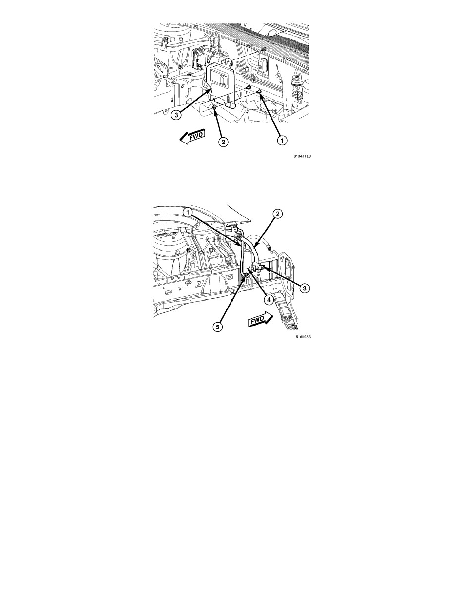
13. If equipped, position the heat shield (3) onto the three studs (1) located on the dash panel in the engine compartment and install the three retaining
nuts (2). Tighten the nuts to 1 Nm (10 in. lbs.).
NOTE: Illustration shown with front fascia and headlamp removed for clarity.
14. Raise and support the vehicle.
15. Install the bolt (3) that secures the upper portion of the A/C suction line (2) to the right front frame rail. Tighten the bolt securely
16. Connect the lower portion of the A/C suction line to the A/C liquid and suction line assembly See: A/C Suction Line - Installation.
17. Connect the rear section of the A/C liquid line (1) to the A/C receiver/drier (4).
18. Install the nut (5) that secures the rear section of the A/C liquid line (1) to the A/C receiver/drier (4). Tighten the nut to 20 Nm (15 ft. lbs.).
19. Reposition the right front wheel house splash shield to the body See: Body and Frame/Fender/Front Fender/Front Fender Liner/Service and
Repair/Splash Shield - Removal.
20. Lower the vehicle.
21. Reconnect the negative battery cable.
22. If equipped with ABS, bleed the brake system See: Brakes and Traction Control/Antilock Brakes / Traction Control Systems/Hydraulic Control
Assembly - Antilock Brakes/Service and Repair/Removal and Replacement/Integrated Control Unit (ICU) - Installation.
CAUTION: Do NOT run the engine with a vacuum pump in operation or with a vacuum present within the A/C system when equipped with
the Denso 6SEU16 variable displacement compressor. Failure to follow this caution will result in serious A/C compressor damage.
23. Evacuate the refrigerant system See: Heating and Air Conditioning/Service and Repair/Refrigerant System Evacuate.
24. Adjust the refrigerant oil level See: Heating and Air Conditioning/Service and Repair/Refrigerant Oil Level.
25. Charge the A/C system See: Heating and Air Conditioning/Service and Repair/Refrigerant System Charge.
Lower A/C Suction Line